3. What’s In the Box
Contained within your Omni I/O package, you will find:
This manual
The Omni I/O
A 9v AC 500 mA “wall wart” power supply
4. Front, Rear, and Top Panel Descriptions
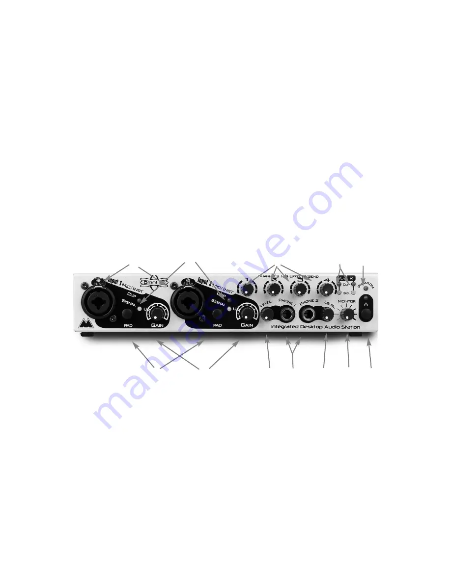
This section identifies the external connections and controls of the Omni I/O
Integrated Desktop Audio Station, with a basic description of their function.
More detailed descriptions of the Omni components and the basics of operation
follow.
4.1 Front Panel
1.
Mic/Instr Inputs 1 & 2: These dual function Neutrik connectors accept either
a male XLR plug for the low impedance microphone inputs, or 1/4” TS
phone plugs for the high impedance instrument inputs. These are the inputs
to the Omni pre-amps.
2.
“Pad” Switch: This is a 20dB gain reduction switch. When pressed and
locked to the
in
position, the corresponding mic or instrument signal,
whichever is in use at the time, will be trimmed by 20dB. Gain reduction is
bypassed when this switch is in the out position.
3.
Signal/Clip LEDs: The “Signal” LED, when lit, indicates the presence of a
signal at the Mic/Instr Inputs 1 & 2, whichever one is in use. The “Clip”
LED will first light when a signal reaches 2dB below clipping.
4
1
2
3
4
5
7
6
8
9
10
11
6


