background image

 MAINTENANCE AND SERVICE SPECIFICATIONS SHEET

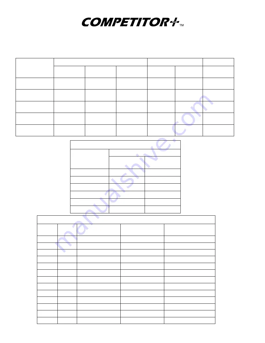
ASSEMBLY CLEARANCES

Metric values (mm) are shown in parentheses ( )

All other values are in inches

LOBES

TO      END

PLATES

LOBE TO CASING

INTERLOBE

MODEL

TOTAL

(MIN./MAX.)

DRIVE END

(MINIMUM)

GEAR END
(MINIMUM)

MINIMUM

MAXIMUM

MININUM

2002, 2004

.005” / .010”

(.13 / .25)

.003”

(.08)

.002”

(.05)

.004”

(.10)

.008”

(.20)

.006”

(.15)

3003, 3006

.005” / .010”

(.13 / .25)

.003”

(.08)

.002”

(.05)

.004”

(.10)

.008”

(.20)

.008”

(.20)

4002, 4005,4007

.007” / .012”

(.18 / .30)

.004”

(.10)

.003”

(.08)

.005”

(.13)

.009”

(.23)

.010”

(.25)

5003, 5006, 5009

.007” / .012”

(.18 / .30)

.004”

(.10)

.003”

(.08)

.005”

(.13)

.009”

(.23)

.012”

(.30)

6005, 6008, 6015

.011” / .015”

(.28 / .38)

.008”

(.20)

.003”

(.08)

.006”

(.15)

.010”

(.25)

.010”

(.25)

MODEL

FLUID OUNCES      (LITERS)

HORIZONTAL

FLOW

VERTICAL

FLOW

2002, 2004

3.5         (.10)

6.0         (.18)

3003, 3006

6.0         (.18)

16.0       (.47)

4002, 4005, 4007

7.0         (.21)

22.8       (.67)

5003, 5006, 5009

16.0       (.47)

27.6       (.82)

6005, 6008, 6015

28.0       (.83)

52.0     (1.54)

MODEL

RPM

PRESSURE

PSI (mbar)

VACUUM

in. Hg (mbar)

TEMPERATURE RISE

F

o

 (C

o

)

2002

5275

12 (825)

14 (475)

225 (125)

2004

5275

7 (480)

14 (475)

185 (103)

3003

3600

12 (825)

14 (475)

170 (94)

3006

3600

7 (480)

14 (475)

115 (64)

4002

3600

15 (1035)

14 (475)

240 (133)

4005

3600

10 (690)

14 (475)

170 (94)

4007

3600

7 (480)

14 (475)

130 (72)

5003

2850

15 (1035)

14 (475)

195 (108)

5006

2850

10 (690)

14 (475)

180 (100)

5009

2850

7 (480)

14 (475)

115 (64)

6005

2350

15 (1035)

16 (540)

250 (139)

6008

2350

12 (827)

16 (540)

240 (133)

6015

2350

6 (415)

12 (410)

130 (72)

14

OIL RESERVOIR CAPACITIES

MAXIMUM OPERATING LIMITS

Summary of Contents for COMPETITOR PLUS 2002

Page 1: ...clearances Polished Sealing Surfaces All shaft surfaces in contact with sealing members are polished to reduce seal wear and risk of leakage Individually Tested Every COMPETITOR PLUS blower is factor...

Page 2: ...5 6 14 19 72 330 476 7 9 20 26 160 304 23 31 307 452 29 38 12 16 16 73 300 445 4 8 16 21 6008 710 1760 2350 207 621 854 2 7 6 8 9 1 176 591 824 5 2 13 17 153 568 801 7 6 19 25 143 557 790 8 9 22 29 11...

Page 3: ...6015 Models INSTALLATION OPERATION MAINTENANCE REPAIR 01 2001 WARNING DO NOT OPERATE BEFORE READING MANUAL LEADING THE SEARCH FOR NEW SOLUTIONS 4840 West Kearney Street P O Box 2877 Springfield Misso...

Page 4: ...scharge openings Blower and drive mounting bolts must be secured Drive belts and coupling guards must be in place Noise level may require ear protection Blower heat can cause burns if touched TUTHILL...

Page 5: ...accidental starting Cover external moving parts with adequate guards Disconnect power before doing any work and avoid bypassing or rendering inoperative any safety or protective devices If blower is...

Page 6: ...reading the service manual and taking adequate safety precautions IMPORTANT Record the blower model and serial numbers of your machine in the OPERATING DATA form below You will save time and expense...

Page 7: ...ble type coupling should be used to connect driver and blower shafts The two shafts must be aligned within 005 13 mm T I R Total Indicated Runout PROTECTIVE MATERIALS Remove protective materials from...

Page 8: ...gular intervals See Suggested Lubrication Intervals for Grease Lubricated Bearings below Use NLGI 2 premium grade petroleum base grease with high temperature resistance and good mechanical stability U...

Page 9: ...nd that these startup procedures be followed in sequence and checked P off in the boxes provided in any of the following cases During initial installation After any shutdown period After maintenance w...

Page 10: ...facturer s recommended pressure Examine relief valve and reset if necessary Replace timing gears See Disassembly and Inspection section on page 10 Excessive blower temperature Too much or too little o...

Page 11: ...ir Operate the blower under a slight load allowing the blower to heat within safe limits The heat generated by the blower will quickly evaporate residual moisture 2 For carpet cleaning applications af...

Page 12: ...lock to break the seal joint Gears are not exposed for visual inspection Items in brackets are referenced to item numbers on page 16 Inspect the gears for the following Broken Teeth Chipped Teeth Unev...

Page 13: ...oved before knocking out the bearings Refer to Figure 7 below A jaw type puller can also be used Refer to Figure 6 below Figure 5 Driving Rotors Out Using Soft Mallet Figure 7 Tapping Bearings Out of...

Page 14: ...Keyway positions are exactly opposite for models 6005 6008 and 6015 DRIVE DRIVEN Place end plate Item 4 on rotors Apply a thin coat of lubricant on the rotor shafts and the inner race of the bearings...

Page 15: ...t rotates as it is moved in or out and the driven rotor turns with it thus changing the clearance between rotor lobes Changing the shim thickness 006 15 mm will change the rotor lobe clearance 003 08...

Page 16: ...006 15 010 25 010 25 MODEL FLUID OUNCES LITERS HORIZONTAL FLOW VERTICAL FLOW 2002 2004 3 5 10 6 0 18 3003 3006 6 0 18 16 0 47 4002 4005 4007 7 0 21 22 8 67 5003 5006 5009 16 0 47 27 6 82 6005 6008 60...

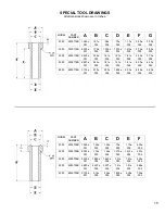
Page 17: ...718B 2 820 001 2 42 005 1 81 005 1 41 005 1 81 005 5 00 005 4 25 005 6000 6500718B 3 135 001 2 73 005 2 00 005 1 605 005 2 00 005 6 25 005 5 50 005 MODEL PART NUMBER A B C D E F 2000 2200708B 1 560 00...

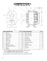
Page 18: ...Timing Gear 2 23 Lip Seal Drive Shaft 1 9 Dowel Pin 4 24 Lip Seal 4 10 Bearing Cover Plate 1 25 Screw Hex Head 4 11 Roller Bearing Drive Shaft 1 26 Washer 2 12 Bearing 1 27 Breather 1 13 Bearing 2 Ite...

Page 19: ...either repair or replace its product part or work at the original Ex works point of shipment or refund an equitable portion of the purchase price The products and parts sold hereunder are not warrant...

Page 20: ...NOTES...

Reviews: