M
a
in
te
n
a
n
c
e
a
n
d
D
is
as
se
m
b
ly
Procedure
Illustration
5)
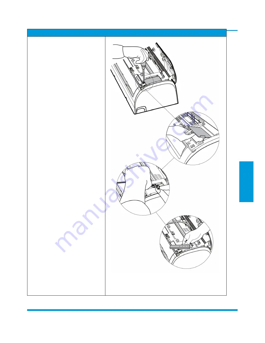
Remove 1 screw and then remove the
electrical cover(see CJ_AF_INV_005-1
and CJ_AF_INV_005-2).
CJ_AF_INV_005-1
CJ_AF_INV_005-2
6)
Disconnect the connector for display
board(see CJ_AF_INV_005-3) .
CJ_AF_INV_005-3
7)
Remove the display board(see
CJ_AF_ INV_005-4).
CJ_AF_INV_005-4
CJ_AF_INV_005
Note:
This section is for reference only. Actual unit appearance may vary.
Page 27
Summary of Contents for ACP-09CH25AEMI/I
Page 1: ...SERVICE MANUAL M DESIGN INVERTER SERIES 2017 SERVICE MANUAL...
Page 2: ......
Page 4: ......
Page 14: ...13 1 17 Information Inquiry 13...


