M
a
in
te
n
a
n
c
e
a
n
d
D
is
as
se
m
b
ly
ACP-24CH70AEMI/O:
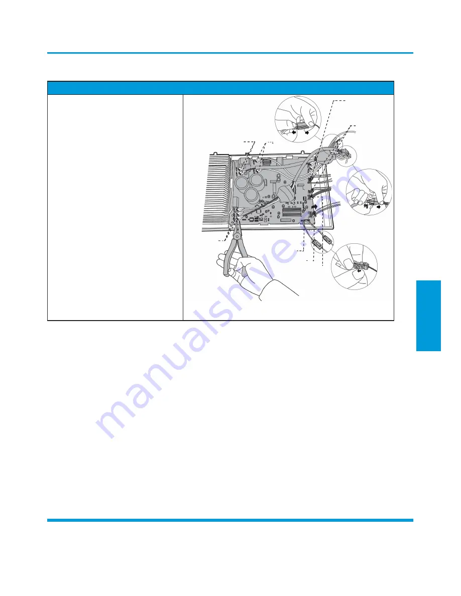
Procedure
Illustration
1)
Remove the connector for the
compressor (see
CJ_ODU_INV_011).
2)
Pull out the two blue wires connected
with the four way valve (see
CJ_ODU_
INV_011).
3)
Pull out connectors of the condenser
coil temp. sensor(T3),outdoor ambient
temp. sensor(T4) and discharge temp.
sensor(T5) (see
CJ_ODU_INV_011).
4)
Disconnect the electronic expansion
valve wire (see Fig
CJ_ODU_INV_011).
5)
Remove the connector for electric
heaters (see Fig
CJ_ODU_INV_011).
Reactor
DR
4-Way Valve
Heaters
6)
Remove the connector for the DR and
reactor (see Fig
CJ_ODU_INV_011).
7)
Then remove the electronic control box
(see Fig
CJ_ODU_INV_011).
Compressor
T3, T4, TP
Fan Motor
Electronic Expansion Valve
CJ_ODU_INV_011
Note:
This section is for reference only. Actual unit appearance may vary.
Page 51
Summary of Contents for ACP-09CH25AEMI/I
Page 1: ...SERVICE MANUAL M DESIGN INVERTER SERIES 2017 SERVICE MANUAL...
Page 2: ......
Page 4: ......
Page 14: ...13 1 17 Information Inquiry 13...


