Instructions for installation and use of ARGENTO
- 6 -
5.
CONVECTION
CURRENT
5.1.
NATURAL CONVECTION AND HOT AIR DUCTS
Please follow the installation guide. The appliance can overheat if
you not apply those instructions.
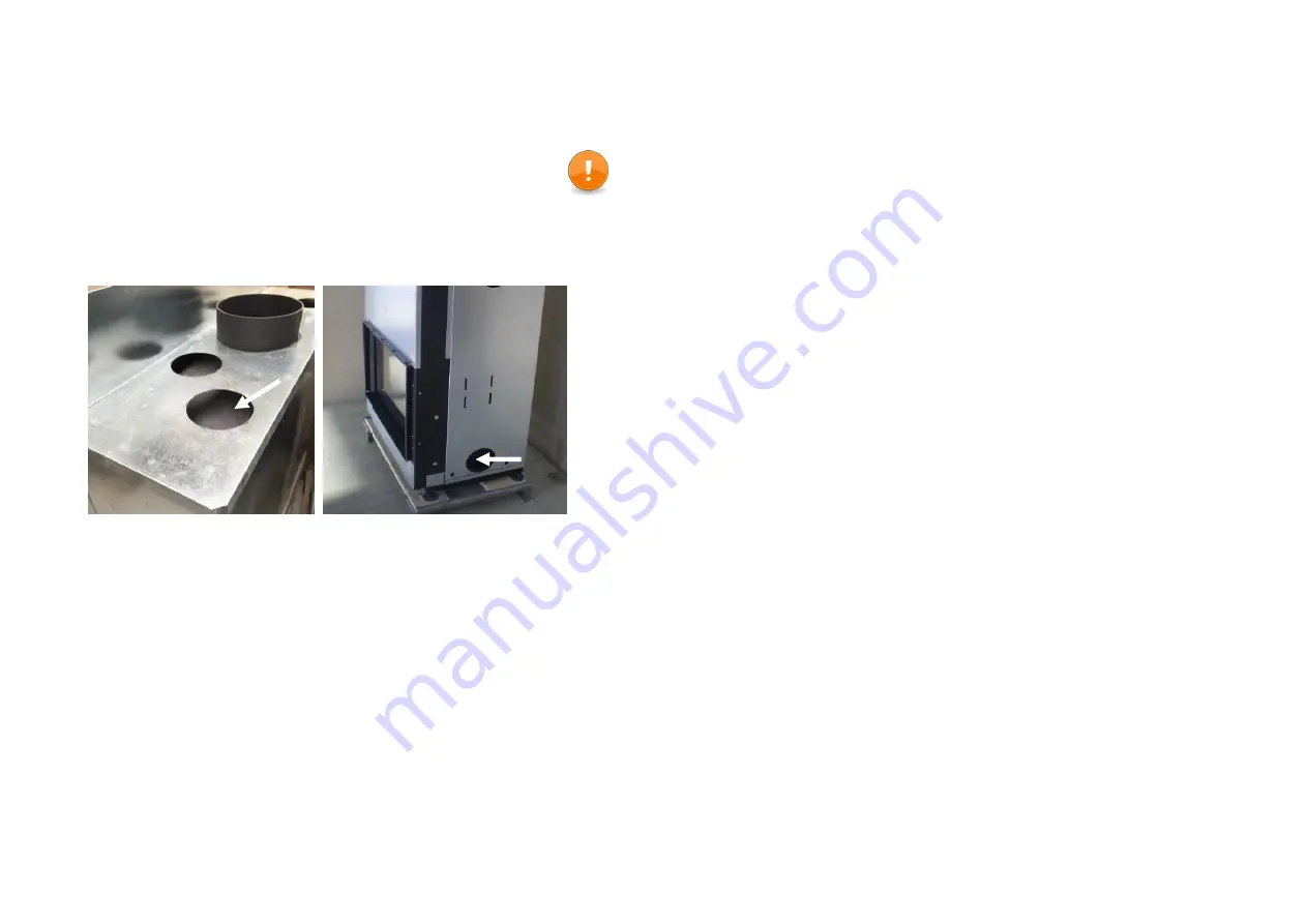
It is compulsory to open hot air vents at the top of the appliance (Pic.13/1).
The entrances for the air supply convection are situated on the bottom side of
the Argento (Pic.13/2) and also through the opening that is provided for the
fan.
The device is placed at least 20 mm above the floor (if placed on the floor) to
allow for natural convection.
A clearance of at least 4 dm
3
, excluding the measurements of a dust filter, or
at least 6 dm
3
, including the measurements of a filter, must be provided for in
the masonry.
The enclosure of the appliance must be provided with ventilation grills or
openings allowing for the elimination of heat by convection. It is possible to
have a convection kit fitted with the appliance. This system directs the heat
inside the room by means of flexible tubes (dia. 150 mm).
Thermally insulated ducts are essential for the optimal functioning of the
appliance (these cause ‘draught’ in the convection air current). By using the
maximum number of ducts (at least 2), the output is improved and the noise
(that is caused by the displacement) is reduced.
For the purposes of the installation of these ducts it is best to go vertically
upwards first for at least 1m and then to change direction, making a rather
wide bend and avoid using a flue terminal grid with a small clearance
because the speed loss that this causes reduces the efficiency of the hot air
vents.
Place all the fittings that you use at the same lengths and angles if possible,
otherwise some grids could give off more heat than others and, seeing that a
hot air pipe functions in a manner similar to a chimney, the one that is hot first
has the most draught and therefore becomes hot even more quickly.
Note:
A circulation of hot air requires that no under-pressure be created in the
room. A grid that is near the floor sees to it that cold air can be drawn in.
Don’t connect those with a flexible. Air will find the way to get at the right
place.
M-design has developed its ideal hot air grids which have many advantages
(Pic. next page) and for the elimination of hot air and the entry of warm air
we advise you to use these Design grills made by M-Design. To simplify the
mounting of the grids you can use the corner profile which is furnished with the
grid. This profile can be mounted on the side of the grid (two little wholes and
screws are provided).
ATTENTION: A house is never completely 100 % dustfree, heating appliances and
warmth circulation creates dust particles. During the periods where you are not using
the fireplace, dust is accumulated in the flexible pipe and the grills. This could cause a
problem with a smell, so we would certainly advise you to clear the flexible and air
inlets and outlets using a vacuum cleaner regularly. The smell caused by these dust
particles will disappear after you have used the fireplace again a few times. This
phenomenon is very common and can be compared to the gray traces appearing
above your radiators. Optionally you can order design metal lids to cover the inlets
and outlets during the summertime.
5.2.
F
AN
Installation:
Remove the Chamotflex plates, the bottom plates and the opening to the fan.
Now slide the fan downwards to just under the stove.
Make the necessary electrical connections.
Fan dimmer:
Leave the adjustment of the fan speed closed.
Fuse 1.5A (Take the knob off, unscrew the little plate, take it out if it is
needed to be replaced.)
The adjustment screw for the minimum speed is under the knob. (M-design has
developed a new induction dimmer which lets the fan run noiselessly and
which may be bought as an option.)
The fan (optional) may be started after the fire has burned for 15 minutes.
Let the fan turn at the maximum speed for 12 hours the first time to let it run
in.
Pic.13


