5
www.m-locks.com
Rotobolt
V03
EN
4
BOLTWORK REQUIREMENTS
The force applied to the boltwork on the lock bolt has to be limited to 1 kN (p. E. by a preconceived
breaking point). Please contact your manufacturer if higher forces are needed. Only use supplied
screws to mount the lock.
The maximum allowed cable/spindle-hole diameter is 11mm (if located
under the lock body)
If the Rotobolt lock is used in conjunction with another lock, the boltwork
must be constructed in a way that the Rotobolt secures first.
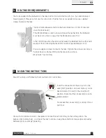
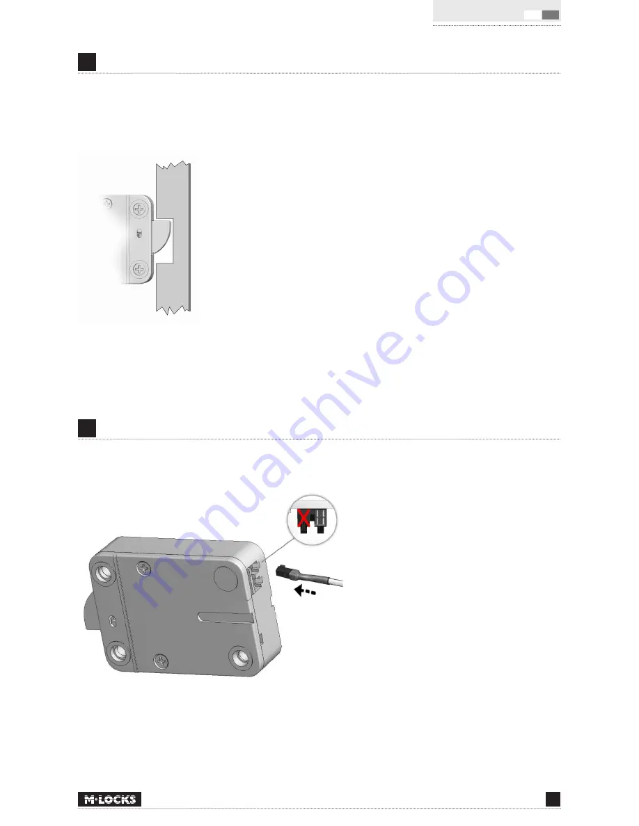
In the LOCKED position the distance between the Rotobolt bolt and the bolt-
work part that is moving the lock bolt should be approximately 1 mm.
Only use supplied screws to mount the lock. Tighten the screws securely so
the lock body is attached firmly to the mounting surface.
(Maximum Torx 5, 5 Nm)
5
MOUNTING INSTRUCTIONS
Mount the entry unit following the manufacturer’s instruction.
Insert the connector of the entry unit in the
outer (ENT) position. Connect battery / alarm
box connector (if used) in the inner (BAT)
position. Check that the connector(s) is com-
pletely seated.
To remove the connector(s), carefully lift and
pull it out.
Connect a 9V alkaline Duracell , Energizer or Duracell Industrial battery to the battery clip to the
keyboard (or battery box) , and check the lock functions . Keep the cable from sharp edges or moving
boltwork parts and set permanently .


