T9530
TechMaster
M-LOCKS BV
Tel: +31 (0)314 376 876
Vlijtstraat 40
ver. 1.0 2013 03 11
Fax: +31 (0)314 376 878
NL-7005 BN Doetinchem
4
www.m-locks.com
Make sure there is an air space on all sides of the lock bolt when the safe’s boltwork is fully
thrown into locked position.
The grooved shaft must extend between 6 and 11mm off the mounting surface: there must be
at least 4mm clearance between the shaft and the lock cover to avoid cable damages during
the use of the lock. The shaft must be deburred well to avoid damage to the cable.
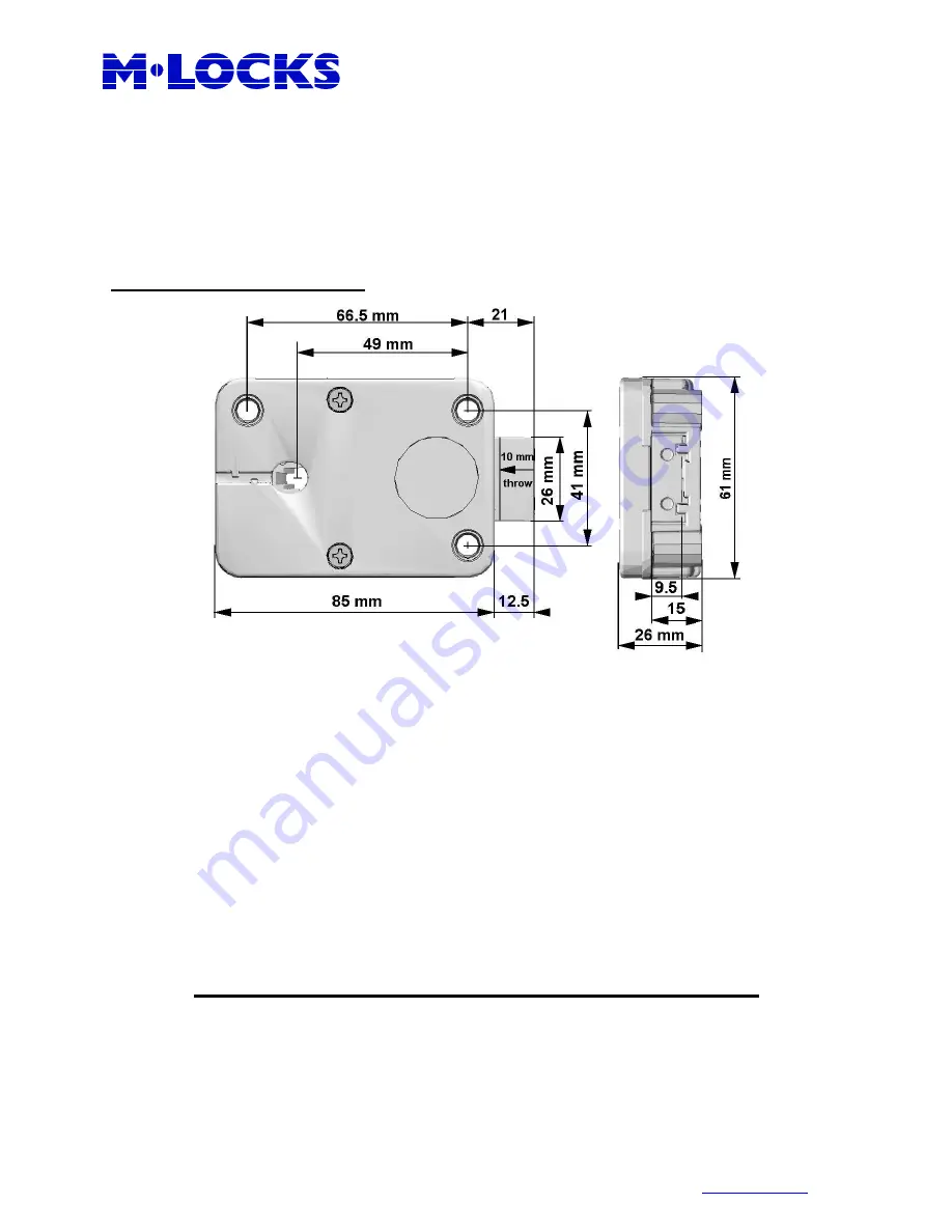
STRAIGHTBOLT DIMENSIONS
Make sure the cable is in the groove. Insert the cable connector into the square hole in the
bottom of the lock and guide it through the hole in the lock cover.
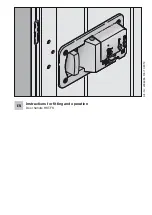
Holding the cable straight place the lock with the square cavity on the grooved shaft and then
screw it to the mounting surface.
Insert the keypad cable into the “ENT” connector of the lock. Check that the cable is
completely seated (to remove it lift it up and carefully pull it out). To tie the cable, push it into
the square groove in the lock cover. Battery box or alarm interfaces will be connected to the
“BAT” connector of the lock.
Connect a 9V-ALKALINE battery and repeat functional test (with door open) several times
before locking the safe door.
Never remove label on lock cover, this voids the warranty.


