background image


MV-RAD 

Page 12 


If in the Advanced Menu, limits have been activated (point 9.11), the tool performs an 

assessment of the follow-up angle.  


In the case of follow-up angle outside tolerance, 

the value is shown in red, the limit concerned is 

mentioned as well 

Upp. Lim.

 resp. 

Low. Lim.

.  


Acknowledge the fault by pressing any key. 


Otherwise the value is shown in green.  


Note that the speed of the tool in test mode is lowered (compared 

to normal operation). 


Even for tight bolt connection, the elastic deformation of the 

reaction arm gives rise to a displayed follow-up angle of ca. 1 to 3°. 

The exact value has to be determined before starting the test routine, and to be 

taken into account for evaluation.  

9.17.


Bolt Documentation System 


The Bolt Documentation System as well is not part of the standard delivery content.  


After purchasing and installation of the software, the Advanced Menu features the 

submenu „Documentation“


Quick access is also possible by pressing both arrow keys simultaneously.  


The following commands are contained in the documentation menu: 

·


View Log File: Inspect data of all boltings completed. 

·


Choose Log File: A new file can be created.  

·


Date/Time: The current time and date can be set, acc. to instructions in 

section 9.18. 

·


Settings: Entry of a user identification (see also point 9.19), and data transfer 

to PC can be activated/disabled. 

·


Program used: The decision between normal and prove program is made in 

this sub-menu (section 9.16)


The following data are saved within the files: 

·


Current number: A number is assigned to each bolting 

disposing of a torque above the minimum tool torque.  

·


Process number: Assigned to each bolt successfully 

tightened in right-handed rotation. 

·


Date and time 

·


Set and real torque 

·


Selected torque unit 

·


Set and real rotating angle 

·


Final torque for rotating angle tightening 

·


Limits selected (see point 9.11) 

·


Total angle and bolting time 

·


Mains voltage and frequency 

·


Program type (normal or prove program) 

·


User (see section 9.19) 


A new file can be created by “Choose

 Log 

File”


Store this file (“

Save

”) to activate it


Pressing key 

M

 for a longer time erases the 

entry.  


When storing an empty entry, the last file 

automatically continues to be used further. 

9.18.


Set Date and Time 


Date and time within the system are displayed and used only with documentation 

feature enabled.  

Summary of Contents for MV-RAD

Page 1: ...M PT Matjeschk PowerTools GmbH Co KG mail m pt de Tel 49 0 35 796 9760 Am Saegewerk 11 www m pt de Subject to technical modifications 01920 Ralbitz Rosenthal Status 07 2022 User Manual MV RAD ...

Page 2: ...9 3 Switching ON __________________________________________________________________ 7 9 4 Main Screen____________________________________________________________________ 7 9 5 General Procedure _____________________________________________________________ 7 9 6 Setting the Torque _____________________________________________________________ 7 9 7 Units _____________________________________________...

Page 3: ...bolts are not detached ______________________________ 16 12 10 Error Message after Completion of Bolting___________________________________ 16 13 Accessories _____________________________________________________________________ 17 13 1 Tool Suspension ______________________________________________________________ 17 13 2 Extension Pieces ____________________________________________________________...

Page 4: ...920 Ralbitz Rosenthal Germany Declare under our sole responsibility that the product Product Name Electric Torque Wrench Series MV RAD is in conformity with the provision of the following EU standards and directives DIN EN 55014 1 2018 08 DIN EN 55014 2 2016 01 DIN EN IEC 61000 3 2 2019 12 DIN EN 61000 3 3 2020 07 DIN EN 62841 1 2016 07 DIN EN 62841 2 2 2015 05 acc to directives 2006 42 EG Appendi...

Page 5: ...lly known rules must be followed prevention of excessive stress heat abrasion or damage caused by sharp edges or moving machine components For outdoor applications also extension cables whenever used must meet the same requirements If operation in humid environment cannot be avoided a fault current circuit breaker is imperative 5 4 Safety of Personnel Persons not participating in the procedure in ...

Page 6: ...e specified on the type plate 9 2 Initial Steps 1 First the reaction arm 2 has to be plugged onto the toothed wheel work 1 as illustrated 2 In order to secure the reaction arm insert the locking ring 3 into the corresponding groove of the gearing 3 The socket 4 has to be shifted onto the integrated square drive bolt Only sockets with standard square opening acc to DIN 3121 should be used 4 Secure ...

Page 7: ...rotation is determined by selector switch 2 Initiate rotation by start button 3 9 6 Setting the Torque The last torque in use is shown immediately after switching ON Default value is 0 Nm The sense of rotation is displayed at the upper left corner as explained above The device type appears at the upper right corner Adjustment of torque is enabled by key M The torque value display changes to yellow...

Page 8: ...ections defined by the user can be stored For standardized HV connections preselections are stored as well but cannot be modified HV relates to high strength prestressed bolts Press M for a longer time to open main menu Press M again to gain access to the menu of preselections Preset Choose between user defined Customerpreset and default HV preselections The following parameters are shown Order nu...

Page 9: ... rotary angle refer to point 9 8 Activation of limits point 9 11 Activation of Bolt Counter point 9 12 Point calibration point 9 14 Selection of units point 9 7 Language point 9 15 System Release consult factory service Bolt Documentation System point 9 17 Lock Advanced Menu 9 11 Limits Before specifying limits themselves activate this function in the Advanced Menu Limits can be defined to each fi...

Page 10: ...eration proceed as follows Choose a new number or Disable the counter If during an activated run the tool is disconnected from the mains it restarts from the current position after switching ON i e the progress is stored in non volatile memory To avoid double counting of bolts tightened already beforehand by erroneously selecting a corresponding bolt a second time it is recommended to use the coun...

Page 11: ...Complete the calibration by pressing and then M 9 15 Languages In the Advanced Menu choose between the following five languages German English Spanish French Dutch After confirmation of the language the device automatically performs restart 9 16 Prove Program The Prove Program is not included in the standard delivery it is available upon request It has been developed for verification of tightened ...

Page 12: ...nu View Log File Inspect data of all boltings completed Choose Log File A new file can be created Date Time The current time and date can be set acc to instructions in section 9 18 Settings Entry of a user identification see also point 9 19 and data transfer to PC can be activated disabled Program used The decision between normal and prove program is made in this sub menu section 9 16 The followin...

Page 13: ...edures carried out after the last maintenance Both counters are subdivided into 0 20 of maximum torque 21 80 81 100 0 100 of maximum torque this is the total value When 20 000 boltings are reached the message Scedule the Maintenance informs the user that the next maintenance routine is required 9 21 Device Information The following information is available here Version no of software Serial no of ...

Page 14: ...MV RAD Page 14 10 Support for Reaction Arm Height of Reaction Arm Support for Reaction Arm Danger of Squeezing ...

Page 15: ...nder Select Port designate the COM port determined in section 11 1 e g COM11 11 4 Read out of Data Activate data connection at the tool itself The feature Data transfer is available in the Settings submenu of the Documentation menu described beforehand Click on Load data During first selection of the tool a particular designation must be assigned e g an inventory number or a distinct name Confirm ...

Page 16: ...t factory service 12 7 No Reaction to Key Commands If the problem cannot be solved by restart the membrane keyboard is defective 12 8 No Reaction to Start Button Possible reasons Torque set to 0 Nm Bolt Counter activated and set to 0 Bolt Counter activated preselected number reached all boltings complete Button itself defective 12 9 In left handed rotation bolts are not detached Possible reasons T...

Page 17: ...rkmanship and becomes null and void in the case of misuse abuse neglect and improper use It is strictly forbidden to manipulate components or to perform repair by means of parts not approved by the manufacturer in writing Improper use or misapplications shall be construed to include excess of any specification of the equipment 15 Maintenance Service 15 1 General Remarks Safety and correct function...

Page 18: ... is available any time 15 5 Calibration The period of validity of the factory calibration amounts to 1 year frequency of use is not taken into consideration 15 6 Manufacturer s Address M PT Matjeschk PowerTools GmbH Co KG Am Saegewerk 11 01920 Ralbitz Rosenthal Germany Phone 49 0 35796 9760 E Mail mail m pt de ...

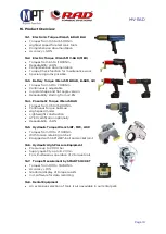
Page 19: ...ng from 2 8 16 4 Pneumatic Torque Wrench RAD Torques from 35 to 15 000Nm Continuous torque build up High speed model Lightweight construction ATEX certification optionally Repeatability 5 0 16 5 Hydraulic Torque Wrench IBT MFC LOW Torques from 110 to 71 000Nm With torsion retaining ratchet Equipped with 360 x180 ball and socket joint 16 6 Hydraulic High Pressure Equipment Pressure up to 2 000 bar ...

Reviews: