48NDVA
5-2-55, Minamitsumori, Nishinari-ku, Osaka 557-0063 JAPAN
Phone: +81(6)6659-8201 Fax: +81(6)6659-8510 E-mail: info@m-system.co.jp
EM-9441-A Rev.9 P. 3 / 9
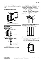
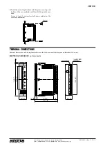
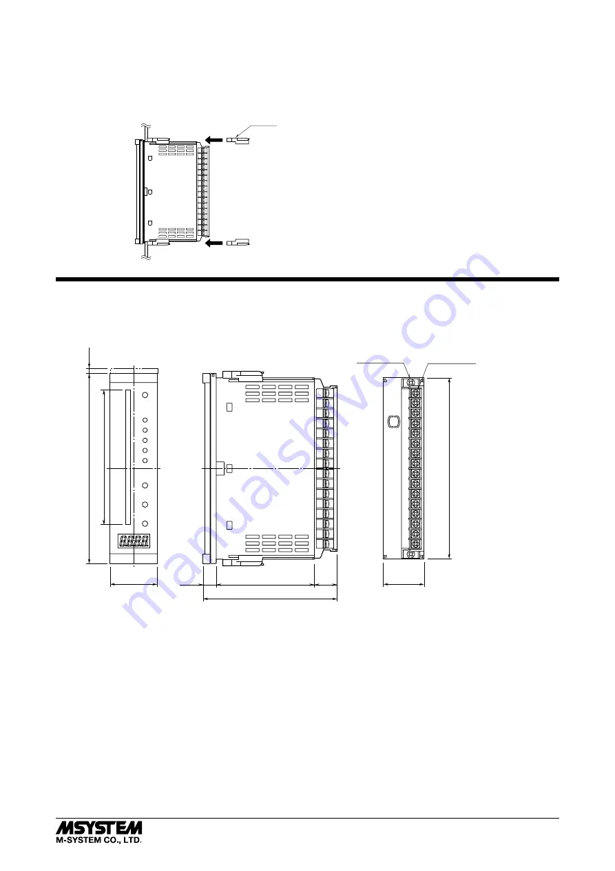
2) Push the mounting brackets into the grooves on top and
bottom of the rear module, until they hit the panel’s rear
side.
Leave at least 3 centimeters both above and below the
unit for ventilation.
Bracket
TERMINAL CONNECTIONS
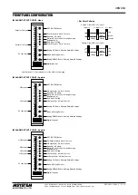
Connect the unit as in the diagram below or refer to the connection diagram on the side of the unit.
■
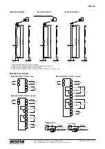
EXTERNAL DIMENSIONS unit: mm (inch)
75 (2.95)
103 (4.06)
10 (.39)
18
(.71)
1
2
3
4
5
6
7
8
9
10
11
12
13
14
15
16
16–M3 SCREW
TERMINALS
2–M3 SCREWS
144 (5.67)
137.5 (5.41)
4
*
1
(.16)
36 (1.42)
31 (1.22)
100 (3.94)
Rounded corners for the option /D
■
OPTION /D BEZEL
*
3
*
1. Space required when replacing the scale plate.
*
2. Used for the existing panel cutout of M-System 48 Series (38 ×
139.5 mm).
*
3. Used for the existing DIN panel cutout (33 × 138 mm)
*
4. Used for the existing panel cutout of Fuji Electric PAJ, PAK, PBA (44 ×
138 mm), etc.
■
STANDARD BEZEL
*
2
10.4
(.41)
7.5
(.30)
3.9
(.15)
136.5 (5.37)
144 (5.67)
11.4
(.45)
7.5
(.30)
4.9
(.19)
136.5 (5.37)
144 (5.67)
8.5
(.33)
10.4
(.41)
7.5
(.30)
136.5 (5.37)
144 (5.67)
■
OPTION /F BEZEL
*
4


