19
DL8 USERS
MANUAL EM-7691-B Rev.24
5. CONNECTING I/O MODULES
5.1 INSTALLATION
The R8 series Remote I/O modules can be used in combination with the DL8. Follow the procedure below to install I/O
modules. Refer also to the instruction manuals of respective I/O modules.
5.1.1 POINTS OF CAUTION
• Switches on the side of I/O modules must be set while the power is removed. DO NOT switch them while the power is
on.
• The DL8 is usable with the R8 module address from 0 to 31. Other addresses cannot be used.
• Modules’ addresses can be chosen regardless of their mounting locations. Be sure not to use duplicated addresses.
• 4-point analog I/O module occupies 2 addresses.
e.g. When R8-SV4 is set to address 5, Input 1 and Input 2 are assigned to address 5, and Input 3 and Input 4
are assigned to address 6. In this case, do not use address 6 for other I/O modules.
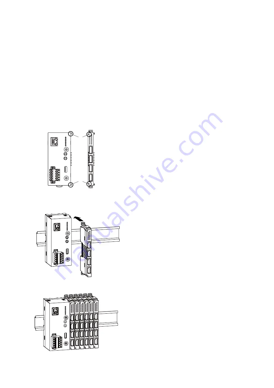
5.1.2 MOUNTING
■
HOW TO MOUNT THE MODULE ON DIN RAIL
A
B
• I/O Module
Confirm that the locking clamps of the I/O module are set.
Insert the module in parallel to the next one while aligning the grooves of
both modules (A & B in the above figure).
Maintain it perpendicularly to the rail.
More I/O modules can be added in the same manner.


