


Model DLA1–xC3
■
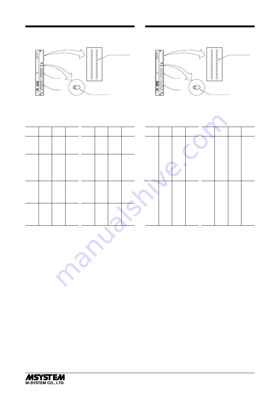
FRONT PANEL (OUTPUT)
Contact Output
Indicator LED
CN2
LED Indicator
Selector
CN1
U
L
SW
External dimensions: See Figure B-1.
■
CONNECTOR PIN ASSIGNMENT (OUTPUT)
CONNECTOR CN1
CONNECTOR CN2
PIN
NO.
CH.
NO.
PIN
NO.
CH.
NO.
PIN
NO.
CH.
NO.
PIN
NO.
CH.
NO.
A1
Do 1
B1
Do17
A1
Do33
B1
Do49
2
2
2
18
2
34
2
50
3
3
3
19
3
35
3
51
4
4
4
20
4
36
4
52
17
C1
17
C5
17
C9
17
C13
5
Do 5
5
Do21
5
Do37
5
Do53
6
6
6
22
6
38
6
54
7
7
7
23
7
39
7
55
8
8
8
24
8
40
8
56
18
C2
18
C6
18
C10
18
C14
9
Do 9
9
Do25
9
Do41
9
Do57
10
10
10
26
10
42
10
58
11
11
11
27
11
43
11
59
12
12
12
28
12
44
12
60
19
C3
19
C7
19
C11
19
C15
13
Do13
13
Do29
13
Do45
13
Do61
14
14
14
30
14
46
14
62
15
15
15
31
15
47
15
63
16
16
16
32
16
48
16
64
20
C4
20
C8
20
C12
20
C16
C1 – C16: negative common per 4 points
Terminal assignment: See Figure B-2.
Model DLA1–xC4
■
FRONT PANEL (OUTPUT)
Contact Output
Indicator LED
CN2
LED Indicator
Selector
CN1
U
L
SW
External dimensions: See Figure B-1.
■
CONNECTOR PIN ASSIGNMENT (OUTPUT)
CONNECTOR CN1
CONNECTOR CN2
PIN
NO.
CH.
NO.
PIN
NO.
CH.
NO.
PIN
NO.
CH.
NO.
PIN
NO.
CH.
NO.
A1
Do 1
B1
Do17
A1
Do33
B1
Do49
2
2
2
18
2
34
2
50
3
3
3
19
3
35
3
51
4
4
4
20
4
36
4
52
5
5
5
21
5
37
5
53
6
6
6
22
6
38
6
54
7
7
7
23
7
39
7
55
8
8
8
24
8
40
8
56
17
C1
17
C1
17
C1
17
C1
18
C1
18
C1
18
C1
18
C1
9
Do 9
9
Do25
9
Do41
9
Do57
10
10
10
26
10
42
10
58
11
11
11
27
11
43
11
59
12
12
12
28
12
44
12
60
13
13
13
29
13
45
13
61
14
14
14
30
14
46
14
62
15
15
15
31
15
47
15
63
16
16
16
32
16
48
16
64
19
C1
19
C1
19
C1
19
C1
20
CL1
20
CL2
20
CL3
20
CL4
C1: negative common to all channels
CL1 – CL4: clamp terminals per 16 points
Terminal assignment: See Figure B-2.
DLA1
5-2-55, Minamitsumori, Nishinari-ku, Osaka 557-0063 JAPAN
Phone: +81(6)6659-8201 Fax: +81(6)6659-8510 E-mail: info@m-system.co.jp
EM-6510 Rev.1 P. 10 / 14


