■
STATION ADDRESS NUMBER (SA)
1. HOW TO SET AN SA
The 2-digit SA number is set at the front with two rotary
switches (SA1 and SA2) for values from 00H up to FFH for a
total of 256 different combinations. The upper switch (SA1)
adjusts the first digit of an SA number. For example, set the
SA1 to “4” and the SA2 to “0” for assigning “40H”.
4
3
2
1
0
F
E D
C
B A
9
8
7
6
5
SA1
4
3
2
1
0
F
E D
C
B A
9
8
7
6
5
SA2
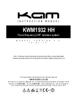
2. HOW TO ASSIGN SA FOR EACH UNIT
2 - 1. Input-only Units and Output-only Units
Input
Output
An output-only unit (code: C1, C2, C3, C4, M1 or U1) re-
ceives its signals from an input-only unit (code: A1, A2, G1
or P1) with the same address.
Identical addresses can be given to many receiving (output-
only) units. A transmitting (input-only) address can be as-
signed only to one unit.
Therefore, when input from one unit is distributed to two or
more output units, all receiving station’s SA must be identi-
cal to the SA of the transmitting unit.
A 64-point input-only unit (code A1) uses an SA set with the
switch and the number plus 1. Do not use this following
number for other units.
Input-only Unit : SA = 40H
Output-only Unit : SA = 40H
[Example]
4
SA1
0
SA2
4
SA1
0
SA2
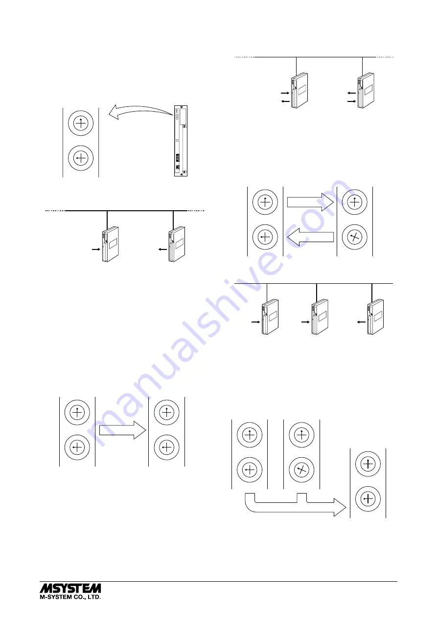
2 - 2. Paired Units
Input
Output
Input
Output
Input/output (dual purpose) units (code: E1, E2, R1 and S1)
can be paired with other dual purpose units with identical
I/O specifications. An even SA number is given to either
unit and this number plus 1 is assigned as SA of the paired
unit.
[Example]
4
SA1
0
SA2
Input/Output Unit : SA = 40H
4
SA1
1
SA2
Input/Output Unit : SA = 41H
2 - 3. Contact 32-point Input Units and 64-point Output Units
Input A
Output
(A + B)
Input B
A 64-point output-only unit (code: C3 and C4) receives its
signals from two input-only units (code A1). Chs. 1 to 32 of
the 64-point output unit are assigned to the signals from
the input-only unit of the identical SA, and Chs. 33 to 64
are assigned to those from the unit of this number plus 1.
4
SA1
0
SA2
SA = 40H
4
SA1
1
SA2
SA = 41H
[Example]
4
SA1
0
SA2
64-point
Output-only Unit
SA = 40H
32-point Input-only Units
DLA1
5-2-55, Minamitsumori, Nishinari-ku, Osaka 557-0063 JAPAN
Phone: +81(6)6659-8201 Fax: +81(6)6659-8510 E-mail: info@m-system.co.jp
EM-6510 Rev.1 P. 3 / 14