background image

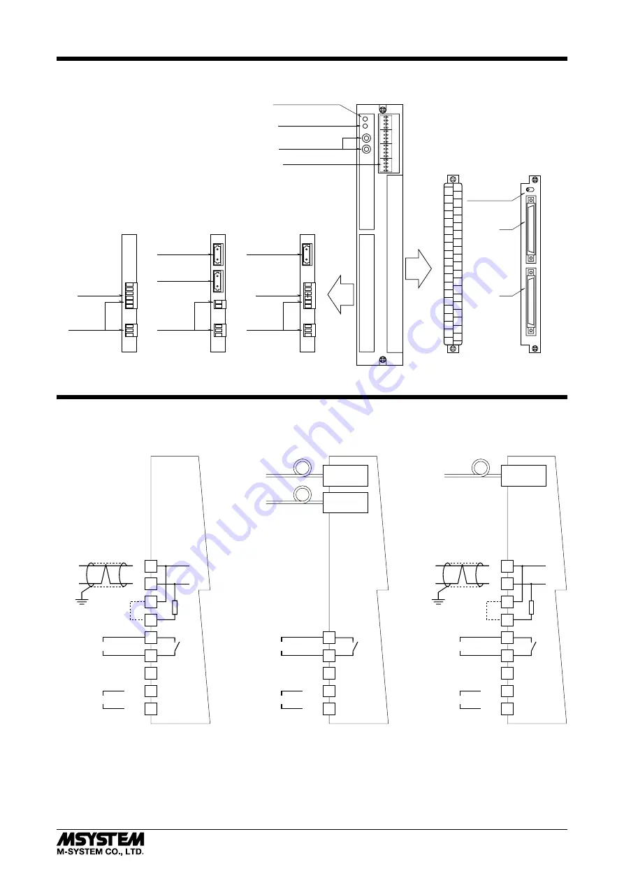
FRONT PANEL CONFIGURATION

SA1

SA2

Power LED Indicator

RUN LED Indicator

I/O Indicator LEDs

(Varies according to I/O types.

See each I/O section.)

Station No. Setting

Rotary Switches

I / O SECTION

(See details to the right)

TRANSMISSION SECTION

(See details to the left)

9
8
7
6
5
4

3
2
1

Jumper

Connector

Terminal

Connector

Terminal

Jumper

Connector

Terminal

Fiber Link

Connector

TWISTED-PAIR & FIBER

STANDARD TYPE

     (40-terminal connector)

DLA1-A2, C3, C4

     (FCN 40-pin connectors)

5
4

3
2
1

Fiber Link

Connector

FIBER OPTICS

9
8
7
6
5
4

3
2
1

TWISTED-PAIR

Fiber Link

Connector

9

8

7

6

5

4

3

2

1

10

11

12

13

14

15

16

25

24

23

22

21

20

19

18

17

26

27

28

29

30

31

32

2

4

6

8

10

12

14

16

18

20

22

24

26

28

30

32

34

36

38

40

1

3

5

7

9

11

13

15

17

19

21

23

25

27

29

31

33

35

37

39

CN1

CN2

U

L

LED Indicator

Selector

 Euro Type

 Euro Type

 Euro Type

TRANSMISSION & POWER CONNECTION DIAGRAM

6

7

8

9

+

V(–)

EARTH (FG)

U(+)

POWER

RUN CONTACT OUTPUT

2

1

5

4

3

JUMPER PIN

*

TWISTED-PAIR CABLE

   (transmission media code: 1)

V(–)

EARTH (FG)

U(+)

POWER

RUN CONTACT OUTPUT

2

1

5

4

3

6

7

8

9

+

V(–)

EARTH (FG)

U(+)

POWER

RUN CONTACT OUTPUT

2

1

5

4

3

TWISTED-

PAIR & FI

BER OPTICS

    (transmission media code: 7)

FIBER - OPTIC

CONNECTOR

FIBER - OPTIC

CONNECTOR

Fiber Optics

FIBER - OPTIC

CONNECTOR

Fiber Optics

FIBER OPTICS CABLE

   (transmission media code: 2)

Shielded

Twisted-pair Cable

JUMPER PIN

*

Shielded

Twisted-pair Cable

*

When the unit is located at the end of transmission line via twisted-pair cable (= no cross-wiring), 

  short across the terminals 6 – 7 with the jumper pin (or wire) provided with the unit.
  Remove the jumper pin for the one not located at the end.

DLA1

5-2-55, Minamitsumori, Nishinari-ku, Osaka 557-0063 JAPAN
Phone: +81(6)6659-8201  Fax: +81(6)6659-8510  E-mail: info@m-system.co.jp

EM-6510  Rev.1  P. 7 / 14

Summary of Contents for DLA1

Page 1: ...move the unit or mount it turn off the power supply and input signal and output signal for safety ENVIRONMENT Indoor use When heavy dust or metal particles are present in the air install the unit insi...

Page 2: ...FICATION Power LED Indicator RUN LED Indicator Fiber Link Connector Station Address Setting Rotary Switches SA1 SA2 Specifications I O Terminal Release Tab RUN Output Terminating Resistor Power Supply...

Page 3: ...with the switch and the number plus 1 Do not use this following number for other units Input only Unit SA 40H Output only Unit SA 40H Example 4 SA1 0 SA2 4 SA1 0 SA2 2 2 Paired Units Input Output Inp...

Page 4: ...ctive covers over the FIBER LINK terminals and connect FIBER LINK connectors Observe appropriate radiuses when bending fiber optic ca bles Follow cable manufacturer s installation procedures Fiber bre...

Page 5: ...units inside twisted pair cable loops Example Remove Keep Keep Keep Keep MOUNTING REQUIREMENTS unit mm inch 55 2 17 55 2 17 288 11 34 2 M4 SCREW 3 5 14 SURFACE MOUNTING SIDE MOUNTING terminal block at...

Page 6: ...Type Connector Terminals 9 8 7 6 5 4 3 2 1 Not provided for fiber optics code 2 Note There is no specific order for connecting fiber optics PIN TERMINAL PHOENIX CONTACT AI 1 5 8BK RECOMMENDED MULTI S...

Page 7: ...1 CN2 U L LED Indicator Selector Euro Type Euro Type Euro Type TRANSMISSION POWER CONNECTION DIAGRAM 6 7 8 9 V EARTH FG U POWER RUN CONTACT OUTPUT 2 1 5 4 3 JUMPER PIN TWISTED PAIR CABLE transmission...

Page 8: ...dimensions See Figure B 1 CONNECTOR PIN ASSIGNMENT INPUT CONNECTOR CN1 CONNECTOR CN2 PIN NO CH NO PIN NO CH NO PIN NO CH NO PIN NO CH NO A1 Di 1 B1 Di17 A1 Di33 B1 Di49 2 2 2 18 2 34 2 50 3 3 3 19 3...

Page 9: ...signment See Figure A 2 Model DLA1 xC2 FRONT PANEL OUTPUT 40 pin Connector Terminal Block Contact Output Indicator LED External dimensions See Figure A 1 CONNECTION DIAGRAM OUTPUT 1 2 3 4 5 6 7 8 9 10...

Page 10: ...t See Figure B 2 Model DLA1 xC4 FRONT PANEL OUTPUT Contact Output Indicator LED CN2 LED Indicator Selector CN1 U L SW External dimensions See Figure B 1 CONNECTOR PIN ASSIGNMENT OUTPUT CONNECTOR CN1 C...

Page 11: ...signment See Figure A 2 Model DLA1 xE2 FRONT PANEL I O 40 pin Connector Terminal Block Contact I O Indicator LED External dimensions See Figure A 1 CONNECTION DIAGRAM I O 1 2 3 4 5 6 7 8 9 10 11 12 13...

Page 12: ...signment See Figure A 2 Model DLA1 xM1 FRONT PANEL OUTPUT 40 pin Connector Terminal Block Modular Jack Output CPU RUN Indicator External dimensions See Figure A 1 CONNECTION DIAGRAM OUTPUT 1 2 3 4 5 6...

Page 13: ...not use Terminal assignment See Figure A 2 Model DLA1 xR1 FRONT PANEL I O 40 pin Connector Terminal Block Modular Jack I O CPU RUN Indicator External dimensions See Figure A 1 CONNECTION DIAGRAM I O 1...

Page 14: ...Output CPU RUN Indicator Pulse Output Indicator LED External dimensions See Figure A 1 CONNECTION DIAGRAM OUTPUT 1 2 3 4 5 6 7 8 9 10 11 12 13 14 15 16 17 18 19 20 21 22 23 24 25 26 27 28 29 30 31 32...

Reviews: