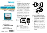
MD7FB
5-2-55, Minamitsumori, Nishinari-ku, Osaka 557-0063 JAPAN
Phone: +81(6)6659-8201 Fax: +81(6)6659-8510 E-mail: info@m-system.co.jp
EM-8066-B Rev.1 P. 2 / 2
INSTALLATION DIAGRAM for CENELEC INTRINSICALLY SAFE MODEL
NOTES
1. The parameters of AA and IS apparatus protected by the MD7FB shall comply with
the following conditions.
Uo
≤
Ui
1
, Ui
2
or Ui
equipment
,
whichever is smallest.
Io
≤
Ii
1
, Ii
2
or Ii
equipment
,
whichever is smallest.
Po
≤
Pi
1
, Pi
2
or Pi
equipment
,
whichever is smallest.
Co
≥
Ci
1
+ Ci
2
+ Ci
equipment
+ Cc
Lo
≥
Li
1
+ Li
2
+ Li
equipment
+ Lc
When multi-drop wiring is used, Ci
2,
Ci
equipment
,
Li
2
and Li
equipment
must be the total capacitance and
inductance of all the apparatus connected to the bus line.
2. Either one of the two MD7FB may be a different lightning surge protector certified by a notified body
under ATEX directive 2014/34/EU.
3. The associated apparatus and the IS apparatus must be certified by a notified body under ATEX
directive 2014/34/EU.
In case of isolated associated apparatus, the earth is not required.
4. When shield wiring is used, it must be connected to earth in the non-hazardous location.
5. Shield wiring method depends on the system requirement.
Maximum Input Power Pi
17.5 V
5.4 W
Maximum Input Inductance Li
Maximum Input Capacitance Ci
Maximum Input Current Ii
Maximum Input Voltage Ui
Electrical Data
Linear Barrier FISCO Supply
any
5 nF
0
μ
H
32 V
400 mA
5 nF
0
μ
H
see right
Maximum Input Power Pi for Linear Barrier:
For T4 and Ta=-25 to 40°C: 1.3W
For T4 and Ta=-25 to 60°C: 1.2W
For T4 and Ta=-25 to 80°C: 1.0W
For T5 and Ta=-25 to 40°C: 1.0W
Non-Hazardous Location
Hazardous Location
Zone 0, 1 and 2
IS Apparatus
*
1,3
DIN rail
4
5
8
Ui
2
Ii
2
Pi
2
Ci
2
Li
2
Cable Capacitance: Cc
Cable Inductance: Lc
*
4
Ui
equipment
Ii
equipment
Pi
equipment
Ci
equipment
Li
equipment
*
5
+
-
+
-
Associated
Apparatus
*
1,3
Uo
Io
Po
Co
Lo
4
5
DIN rail
Ui
1
Ii
1
Pi
1
Ci
1
Li
1
MD7FB
*
5
1
2
7
+
3
-
SHLD
6
6
8
Bus Line
1
2
3
MD7FB
*
2
*
2


