background image

22

EK 10

Italiano

English

Français

F

-

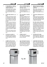
COLLEGAMENTO TUBO EVA-
CUAZIONE ESTERNA  (SOLO PER
VERSIONE ASPIRANTE)

Collegare il tubo di evacuazione
alla condotta esterna e fissarlo
con una fascetta stringitubo.
Non montare i filtri a carbone at-
tivo.

G

-

CONNESSIONE ELETTRICA ALLA
RETE:

Verificare che la tensione di rete
sia adeguata a quella richiesta
par l'alimentazione della cappa
come indicato sulla targhetta
applicata all'interno dell' appa-
recchio.
Montare sul cavo una spina a
norma e adeguata al carico da
sopportare oppure, nel caso di
collegamento diretto alla rete,
interporre tra la rete e l'apparec-
chio un interruttore bipolare a
norma e di potenza adeguata con
apertura minima fra i contatti di
3mm.
Il cavo di terra gallo/verde (se
presente) non deve essere inter-
rotto.

H

-

CONTROLLO FUNZIONALE:

Verificare l'accensione del moto-
re nelle tre velocita' (4 velocità per
versione elettronica) e l'illumina-
zione.

I

-

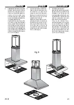
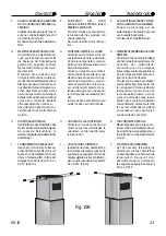
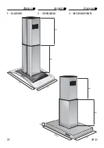
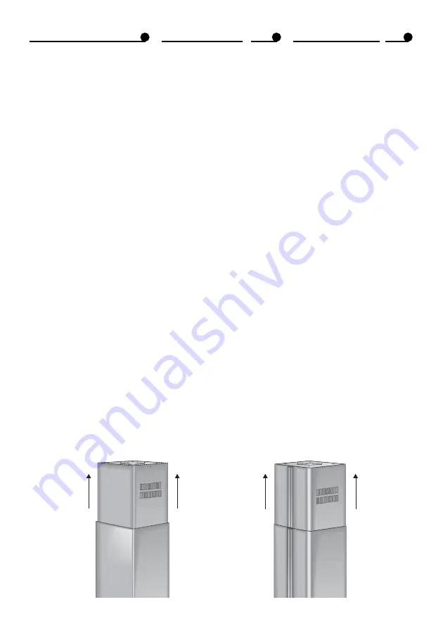
POSIZIONAMENTO CAMINI:

Sollevare verso l'alto, fino al sof-
fitto, il camino telescopico supe-
riore (quello con le asolature) e
fissarlo al traliccio telescopico
superiore utilizzando le viti in do-
tazione M 4.2 x 9.5 TC  (Fig.10).

f

-

HOW TO CONNECt THE EXTER-
NAL EXHAUST PIPE (ONLY FOR
ASPIRATING TYPES)

Connect the exhaust pipe to the
external duct and fix it by means
of a pipe tightening ring.
Do not use activated carbon fil-
ters.

G

-

HOW TO CONNECT TO THE ELEC-
TRICAL MAIN:

Check to see that the main volt-
age complies with the one re-
quired by the hood, which is indi-
cated on the tag that is applied
on the internal side of the appli-
ance.
Assemble a suitable plug on the
wire or insert a proper power
two-pole switch if it is to be directly
connected to the main with a 3mm
minimum opening between
contacts between the main and
the appliance. All the above-men-
tioned electrical parts must com-
ply with the current standards.
The yellow/green earthing cable
(if included) must not be inter-
rupted.

H

-

OPERATING CHECKS:

-

Check lights and motor start-up
on all 3 speeds (the electronic
type has 4 speeds) .

I

-

HOW TO POSITION THE STACKS:

Lift the upper telescopic stack (the
one with slots) upwards towards
the ceiling and fix it by means of
the  M 4.2 x 9.5 TC  screws in-
cluded in the supply (Fig.10).

F

- LIAISON TUYAU EVACUATION EX-

TERNE (SEULEMENT POUR VERSION
ASPIRANTE)

Relier le tuyau d’évacuation à la
conduite externe et le fixer avec une
petite bande presse-tuyau.
Ne pas monter les fitres à charbon
actif.

G - CONNECTION ELECTRIQUE AU RE-

SEAU:

Vérifier que la tension de réseau
corresponde à celle qui est deman-
dée pour l’alimentation de la hotte
comme indiqué sur la plaque située
à l’intérieur de l’appareil.

Sur le câble monter une fiche selon
les règles, indiquée pour la charge
à supporter ou, dans le cas de
liaison directe avec le réseau, pla-
cer, entre le réseau et l’appareil, un
interrupteur bipolaire selon les rè-
gles et avec une puissance adé-
quate et une ouverture minimum
entre les contacts de 3mm.
Le câble de terre jaune/vert (s’il
existe) ne doit pas pas être inter-
rompu.

H - CONTROLE FONCTIONNEL:

Vérifier l’allumage du moteur dans
les trois vitesses (4 vitesses pour
version électronique) et l’illumina-
tion.

I

- POSITIONNEMENT CHEMINEES:

Soulever vers le haut, jusqu’au pla-
fond, la cheminée télescopique
supérieure (celle qui a les  bouton-
nières) et la fixer au pylône télesco-
pique supérieur en utilisant les vis
en dotation M 4.2 x 9.5 TC  (Fig.10).

Fig. 10A

Summary of Contents for PLANA ISOLA

Page 1: ...nutenzione Use and maintenance instructions Instructions pour l utili sation et manutention Bedienungs und Wartungsanleitung Instrucciones para el uso y mantenimiento Gebruiksaanwijzingvoorde afzuigka...

Page 2: ...AGE 8 2 3 carbon filter PAGE10 2 4 lighting PAGE 10 3 INSTALLING INSTRUCTIONS PAGE12 3 1 general PAGE12 3 2 safety PAGE12 3 3 components PAGE12 3 4 installation PAGE16 4 CONSTRUCTIONANDTECHNICAL SPECI...

Page 3: ...S 9 2 3 KOHLENSTOFFILTER S 11 2 4 BELEUCHTUNG S 11 3 HINWEISEZURINSTALLATION S 14 3 1 ALLGEMEINES S 14 3 2 SICHERHEIT S 14 3 3 BAUTEILE S 14 3 4INSTALLATION S 17 4 TECHNISCHEUND KONSTRUKTIVESPEZIFIKE...

Page 4: ...st speed pushbutton D Aspiration 2 nd speed pushbutton E Aspiration 3 nd speed pushbutton F Light pushbutton 1 2 ELECTRONIC CONTROL PANEL A Light pushbutton B 1st speed ON OFF pushbutton C 2nd speed O...

Page 5: ...Pulsador primera velocidad de aspiraci n D Pulsador segunda velocidad de aspiraci n E Pulsadorterceravelocidaddeaspi raci n F Pulsador iluminaci n 1 2 CUADRO MANDOS ELECTR NICO A Pulsador iluminaci n...

Page 6: ...ed by electrical power are being used while the hood is on E Do not leave the cooker on if it is not being used F The hood has been designed to remove the kitchen smells any other additional use shall...

Page 7: ...po la campana y otros aparatos no alimentados el ctricamente ventilar bien el local E Apagar los quemadores si no se van a usar F Usar la campana solo para lo que ha sido creada eliminar los malos olo...

Page 8: ...NZA Prima di procedere a qualsiasi operazione di manutenzione scollegarel apparecchiodalcolle gamento elettrico sfilando la spi na o agendo sull interruttore ge nerale 2 2 FILTRI ANTIGRASSO METALLICI...

Page 9: ...ncias abrasivas 2 MANTENIMIENTO 2 1 ADVERTENCIAS Antes de realizar cualquier tipo de mantenimiento desenchu far el aparato o quitar los plo mos 2 2 FILTROS ANTIGRASA METALICOS Lavar los filtros por lo...

Page 10: ...ter then assemble the new filter Type3 Fig 2C Disassemblethemetalanti greasefilters Rotate the filter for approx 90 and remove it For assembly slide the new filter in thenibonthesideofthemotorand then...

Page 11: ...ntfernen Sie die beiden Metallbefestigungen nehmen Sie denFilterherausundbauenSieden neuen Filter ein Version3 Abb 2C die Metallfettfilter auszubauen den Filter um 90 zu drehen und heraus zu ziehen de...

Page 12: ...ine toute res ponsabilit pour dommages dus une installation qui n a pas t effectu e correctement ou con form ment aux r gles de l art 3 2 SECURITE A Ne pas relier l appareil aux con duitsd vacuationde...

Page 13: ...EK 10 13 Nederlands Deutsch Espa ol A B B C C E D A B B C C D E A B B C C E D...

Page 14: ...14 EK 10 Italiano English Fran ais A B B C C E D A B B C C D E A B B C C E D...

Page 15: ...ltigen Vorschriften sowie im Besonderen die in Bezug auf den Ausla der abzuleitenden Luft zu beachten sind Der Hersteller lehnt jegliche Verantwortung f r Sch denaufGrundeinerfalschen oder nicht fachg...

Page 16: ...port by means of the four M 5x40 screws with the plastic inserts sup plied washers after making 4 holes of dia 8mm centre distance 160 x 180 Fig 4 B HOWTOASSEMBLETHELOWER TELESCOPIC TRESTLE TO THE HOO...

Page 17: ...eriorusandoloscuatrotacosde pl stico y tornillos de M 5x40 las arandelas tras haber hecho cuatro agujerosdedi metro 8mmeje160 x 180 Fig 4 B COLOCACION DEL ARMAZON TELESCOPICO INFERIOR EN EL CUERPO DE...

Page 18: ...S Use a 125 150 pipe flexible if possible then fix it with a pipe tightening ring Fig 6 D HOWTOARRANGETHESTACKS Slidetheuppertelescopic theone with slots on the outside the lower telescopic trestle Sl...

Page 19: ...etarlo con una abrazaderaalempalmedereduc ci n Fig 6 D CHIMENEAS Meter la chimenea telesc pica su perior la que tiene los agujeros en forma de hojal en el exterior del armaz n telesc pico inferior Met...

Page 20: ...ks that havealreadybeenpositioned on theoutsideoftheuppertelescopic trestle that has been previously fixed to the ceiling Fig 8 Arrange the overall at the proper heightrememberingthatthedis tancebetwe...

Page 21: ...as en el exterior del armaz n telesc pico superior que hemos sujetado al techo Fig 8 Regular la altura de todos los com ponentes teniendo en cuenta que la distancia entre el plano de coc ci nylapartei...

Page 22: ...able plug on the wire or insert a proper power two poleswitchifitistobedirectly connectedtothemainwitha3mm minimum opening between contacts between the main and theappliance Alltheabove men tioned ele...

Page 23: ...a el ctrica necesaria para el funcio namiento del aparato o si se co necta directamente a la red colo car un interruptor bipolar de po tencia adecuada con una apertu ra m nima entre los contactos de 3...

Page 24: ...OPERATINGSPEEDS THEELECTRONIC TYPEHAS4SPEEDS ACTIVATED CARBON FILTER WITH HIGH DEPURATING QUALITIES FILTERING TYPES COOKING COUNTER LIGHTING SYSTEM RAI ANTIJAMMING REFERENCE STANDARDS ACCORD INGTOTHEE...

Page 25: ...ESCHWINDIGKEITEN 4 Geschwindigkeiten bei elektronischer Ausf hrung AKTIVKOHLENFILTETR MIT HOHER REINIGUNGSLEISTUNG FILTER VERSION BELEUCHTUNGSANLAGEF RKOCH FL CHE FUNKENTST RUNG BEZUGSSTANDARD HINSICH...

Page 26: ...26 EK 10 Italiano English Fran ais 5 INGOMBRI 5 DIMENSIONS 5 ENCOMBREMENTS 600 900 500 60 500 500 900 600 600 500...

Page 27: ...EK 10 27 Nederlands Deutsch Espa ol 5 PLATZBEDARF 5 MEDIDAS TRANSVERSALES 5 OBSTAKELS 500 500 600 900 500 35 270...

Page 28: ...28 EK 10 Italiano English Fran ais GRAFICA E STAMPA SERIART FABRIANO AN ITALY 0039 732 23069...

Reviews: