R3-ND3
5-2-55, Minamitsumori, Nishinari-ku, Osaka 557-0063 JAPAN
Phone: +81(6)6659-8201 Fax: +81(6)6659-8510 E-mail: info@m-system.co.jp
EM-8382 Rev.11 P. 5 / 6
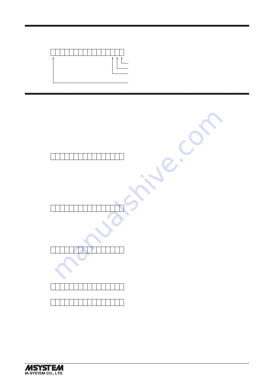
MODULE STATUS, ERROR STATUS, DATA ERROR STATUS
Shows each module’s availability and error status.
0
15
Module 1
Module 2
Module 3
:
Module 16
I/O DATA DESCRIPTIONS
The data allocations for typical I/O modules are shown below.
Refer to the manual for each module for detailed data allocations.
■
ANALOG DATA (16-bit data, models: R3-SV4, YV4, DS4, YS4 and US4, etc.)
16-bit binary data.
Basically, 0 to 100% of the selected I/O range is converted into 0 to 10000 (binary).
-15 to 0 % is a negative range represented in 2’s complement.
In case of R3-US4, -10 to 0% is a negative range represented in 2’s complement.
0
15
■
TEMPERATURE DATA (16-bit data, models: R3-RS4, TS4 and US4, etc.)
16-bit binary data.
With °C temperature unit, raw data is multiplied by 10. For example, 25.5°C is converted into 255.
With °F temperature unit, the integer section of raw data is directly converted into the data. For example, 135.4°F is con-
verted into 135.
Minus temperature is converted into negative values, represented in 2’s complements.
0
15
■
ANALOG DATA (16-bit data, models: R3-CT4A, CT4B, etc.)
16-bit binary data.
Integer obtained by multiplying unit value (A) by 100.
In case of CLSE-R5, integer obtained by multiplying unit value (A) by 1000.
0
15
■
ACCUMULATED COUNT DATA (32-bit data, models: R3-PA2, PA4A, WT1, WT4, etc.)
32-bit binary data is used for accumulated counts and encoder positions.
Lower 16 bits are allocated from the lowest address to higher ones, higher 16 bits in turn.
0
15
+0
Lower 16 bits
0
15
+1
Higher 16 bits


