background image

R3-NF3

5-2-55, Minamitsumori, Nishinari-ku, Osaka 557-0063 JAPAN
Phone: +81(6)6659-8201  Fax: +81(6)6659-8510  E-mail: info@m-system.co.jp

EM-8288  Rev.2  P. 4 / 8

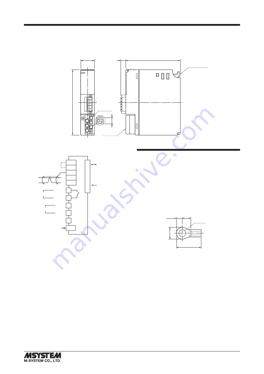
TERMINAL CONNECTIONS

Connect the unit as in the diagram below.


EXTERNAL DIMENSIONS  unit: mm (inch) 

130 (5.12)

27.5 (1.08)

109 (4.29)

10 (.39)

1

2

3

4

5

6

TERMINAL

COVER

6–M3

SCREW

6.2

(.24)

POSITIONING

GUIDE


CONNECTION DIAGRAM

INTERNAL POWER

INTERNAL


BUS

CONFIGURATION JACK

JACK

BUS CONNECTOR

*  

When the module is at an end of the transmission line via

    twisted-pair cable (= when there is no cross wiring), close
    across the RT+ and RT– terminals with the jumper included
    in the product package.  Remove the jumper for all other locations.

**

Not provided with ‘No Power Supply’ type module.

Caution: FG terminal is NOT a protective conductor terminal.

1

4

RUN 

+

RUN 

RUN CONTACT OUTPUT

2

3

6

U (+) 

V (–) 

FG

POWER INPUT

**

**

RT+
RT–

SD

T2
T1

To Other

T-Link

Devices


+

Shielded Twisted-pair

Cable

Close to terminate

*

WIRING INSTRUCTIONS


M3 SCREW TERMINAL (power input, RUN contact output) 

Torque: 0.5 N·m


SOLDERLESS TERMINAL 

Refer to the drawing below for recommended ring tongue 
terminal size.  Spade tongue type is also applicable.  Solder-
less terminals with insulation sleeve do not fit.
Recommended manufacturer: Japan Solderless Terminal 
MFG.Co.Ltd, Nichifu Co.,ltd
Applicable wire size: 0.75 to 1.25 mm

2

12max

6max

3max

4min

3.2 dia.

(mm)


EURO TYPE CONNECTOR TERMINAL (T-Link)

Applicable wire size: 0.2 to 2.5 mm

2

 (AWG24 to 12)

Stripped length: 7 mm

Summary of Contents for R3-NF3

Page 1: ... ventilation Do not install the unit where it is subjected to continuous vibration Do not subject the unit to physical impact Environmental temperature must be within 10 to 55 C 14 to 131 F with relative humidity within 30 to 90 RH in order to ensure adequate life span and operation WIRING Do not install cables close to noise sources relay drive cable high frequency line etc Do not bind these cabl...

Page 2: ...tor Terminal FRONT ROTARY SW Node Address SA1 SA2 Node Address is set in decimal Setpoint adjustment 00 99 FRONT DIP SW Factory Setting I O Points setting KS0 KS1 SW I O POINTS DIGITAL 16 POINTS DIGITAL 32 POINTS DIGITAL 64 POINTS DIGITAL 256 POINTS ANALOG 4 POINTS ANALOG 8 POINTS ANALOG 16 POINTS ANALOG 64 POINTS KS0 OFF ON OFF ON KS1 OFF OFF ON ON Data setting KS2 SW DATA DIGITAL ANALOG KS2 OFF ...

Page 3: ... must be Main OFF network and the other must be Sub ON net work For single communication the network module must always be set to Main OFF SW DUAL COMMUNICATION MAIN SUB SW3 1 OFF ON Input Error Data setting SW3 2 Hold When the communication from an input module is lost due to the input module error the network module holds the signal and stands by until the communication recovers Set to 0 When th...

Page 4: ...ackage Remove the jumper for all other locations Not provided with No Power Supply type module Caution FG terminal is NOT a protective conductor terminal 1 4 RUN RUN RUN CONTACT OUTPUT 2 3 6 U V FG POWER INPUT RT RT SD T2 T1 To Other T Link Devices Shielded Twisted pair Cable Close to terminate WIRING INSTRUCTIONS M3 SCREW TERMINAL power input RUN contact output Torque 0 5 N m SOLDERLESS TERMINAL ...

Page 5: ... shown below Slot 1 4 Slot 2 4 Slot 3 4 Slot 4 1 Slot 5 1 Slot 6 1 Slot 7 1 Then the I O data are assigned as in the figures below IN THE CASE OF NO I O MODULE STATUS KS3 OFF I O TYPE INPUT ONLY or OUTPUT ONLY The side DIP SW SW1 2 determine data allocation of module number of data per module The number of data set by SW1 and SW2 is assigned to transmission data in order from slot 1 0 15 0 2 4 6 8...

Page 6: ...gned because there is no input data For output only operate without status area Module Status indicates whether individual I O modules are mounted or not The bit corresponding to the mounted slot turns to 1 and the unmounted slot to 0 Error Status indicates error status for each module as described below The bit corresponding to such module turns to 1 R3 TSx R3 RSx R3 US4 T C RTD input Input burno...

Page 7: ... example 135 4 F is con verted into 135 Minus temperature is converted into negative values represented in 2 s complements 0 15 ANALOG DATA 16 bit data models R3 CT4A CT4B etc 16 bit binary data Integer obtained by multiplying unit value A by 100 In case of CLSE R5 integer obtained by multiplying unit value A by 1000 0 15 ACCUMULATED COUNT DATA 32 bit data models R3 PA2 PA4A WT1 WT4 etc 32 bit bin...

Page 8: ...ri ku Osaka 557 0063 JAPAN Phone 81 6 6659 8201 Fax 81 6 6659 8510 E mail info m system co jp EM 8288 Rev 2 P 8 8 DISCRETE DATA models R3 DA16 DC16 etc 0 15 Input 1 Output 1 Input 2 Output 2 Input 3 Output 3 Input 16 Output 16 0 OFF 1 ON ...

Reviews: