R3-TC2
5-2-55, Minamitsumori, Nishinari-ku, Osaka 557-0063 JAPAN
Phone: +81(6)6659-8201 Fax: +81(6)6659-8510 E-mail: info@m-system.co.jp
EM-8468 Rev.3 P. 36 / 37
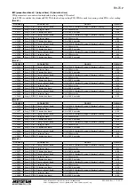
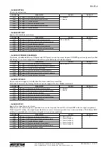
• ALARM SETTING
Choose alarm functions.
ADDRESS
PARAMETER
RANGE
DEFAULT
+256
CT input 1, Heater wire break alarm
0 : Disable
1 : Enable
0
+262
CT input 1, SSR shortcircuit failure alarm
+268
CT input 1, Overload alarm
+512
CT input 2, Heater wire break alarm
+518
CT input 2, SSR shortcircuit failure alarm
+524
CT input 2, Overload alarm
• ALARM SETPOINT
Specify a threshold for each alarm.
ADDRESS
PARAMETER
RANGE
DEFAULT
+257
CT input 1, Heater wire break alarm setpoint
0.0 to 600.0 A
0.0
+263
CT input 1, SSR shortcircuit failure alarm setpoint
+269
CT input 1, Overload alarm setpoint
+513
CT input 2, Heater wire break alarm setpoint
+519
CT input 2, SSR shortcircuit failure alarm setpoint
+525
CT input 2, Overload alarm setpoint
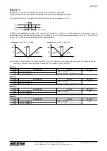
• ALARM HYSTERESIS (DEADBAND)
Hysteresis, a deadband between ON point and OFF point, is used to prevent frequent ON/OFF operations (generally called
‘chattering’) of an alarm output device when the current fluctuates around the setpoint.
ADDRESS
PARAMETER
RANGE
DEFAULT
+258
CT input 1, Heater wire break alarm hysteresis
0.0 to 99.9 A
0.0
+264
CT input 1, SSR shortcircuit failure alarm hysteresis
+270
CT input 1, Overload alarm hysteresis
+514
CT input 2, Heater wire break alarm hysteresis
+520
CT input 2, SSR shortcircuit failure alarm hysteresis
+526
CT input 2, Overload alarm hysteresis
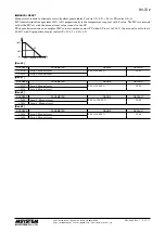
• ALARM LATCHING
Once an alarm is tripped, it is held when the alarm condition is cancelled.
Latched alarm is reset by turning the device’s power supply off or by a Modbus command.
ADDRESS
PARAMETER
RANGE
DEFAULT
+259
CT input 1, Heater wire break alarm latching
0 : Disable
1 : Enable
0
+265
CT input 1, SSR shortcircuit failure alarm latching
+271
CT input 1, Overload alarm latching
+515
CT input 2, Heater wire break alarm latching
+521
CT input 2, SSR shortcircuit failure alarm latching
+527
CT input 2, Overload alarm latching
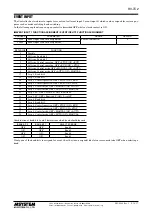
• ALARM OUTPUT
Specify the output device for alarms.
When one of the control outputs is specified, be sure also to specify ‘Alarm OR’ or ‘Alarm AND’ with its output assignment.
With ‘Alarm OR’ setting, the output is provided if one or more alarms assigned to it are in true conditions. With ‘Alarm AND’
setting it is provided only if all alarms assigned to it are in true conditions.
ADDRESS
PARAMETER
RANGE
DEFAULT
+260
CT input 1, Heater wire break alarm output
0 : Network only
1 : Control output 1
2 : Control output 2
3 : Control output 3
4 : Control output 4
0
+266
CT input 1, SSR shortcircuit failure alarm output
+272
CT input 1, Overload alarm output
+516
CT input 2, Heater wire break alarm output
+522
CT input 2, SSR shortcircuit failure alarm output
+528
CT input 2, Overload alarm output

