R3-TC2
5-2-55, Minamitsumori, Nishinari-ku, Osaka 557-0063 JAPAN
Phone: +81(6)6659-8201 Fax: +81(6)6659-8510 E-mail: info@m-system.co.jp
EM-8468 Rev.3 P. 34 / 37
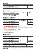
EVENT INPUT
The Controller has two discrete inputs for event control (event input 1, event input 2) which can be assigned for various pur-
poses such as mode switching, bank switching.
In the following explanations, an open contact is described OFF, while a closed contact is ON.
■
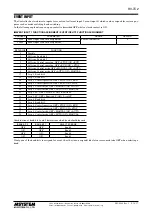
EVENT INPUT 1 FUNCTION ASSIGNMENT / EVENT INPUT 2 FUNCTION ASSIGNMENT
ADDRESS
PARAMETER
RANGE
DEFAULT
+1248
Event input 1 function assignment
See the table below.
0
+1408
Event input 2 function assignment
SET VALUE
FUNCTION
0
Disable
1
All loops, Bank bit 0
2
All loops, Bank bit 1
3
All loops, Control operation: OFF = STOP / ON = RUN
4
All loops, Control operation: OFF = RUN / ON = STOP
5
All loops, Control mode: OFF = MANUAL / ON = AUTO
6
All loops, Control mode: OFF = AUTO / ON = MANUAL
17
Loop 1, Bank bit 0
18
Loop 1, Bank bit 1
19
Loop 1, Control operation: OFF = STOP / ON = RUN
20
Loop 1, Control operation: OFF = RUN / ON = STOP
21
Loop 1, Control mode: OFF = MANUAL / ON = AUTO
22
Loop 1, Control mode: OFF = AUTO / ON = MANUAL
23
Loop 1, SP: OFF = Local SP / ON = Remote SP
24
Loop 1, SP: OFF = Remote SP / ON = Local SP
33
Loop 2, Bank bit 0
34
Loop 2, Bank bit 1
35
Loop 2, Control operation: OFF = STOP / ON = RUN
36
Loop 2, Control operation: OFF = RUN / ON = STOP
37
Loop 2, Control mode: OFF = MANUAL / ON = AUTO
38
Loop 2, Control mode: OFF = AUTO / ON = MANUAL
Combination of bank bit 0 and 1 determines which bank should be used.
BANK BIT 0
BANK BIT 1
SELECTED BANK
OFF
OFF
Bank 0
ON
OFF
Bank 1
OFF
ON
Bank 2
ON
ON
Bank 3
If only one of the bank bits is assigned for event, the other (non-assigned) bit status is assumed to be OFF when selecting a
bank.

