R7G-SC-SHL
5-2-55, Minamitsumori, Nishinari-ku, Osaka 557-0063 JAPAN
Phone: +81(6)6659-8201 Fax: +81(6)6659-8510 E-mail: info@m-system.co.jp
EM-7817-A Rev.2 P. 5 / 7
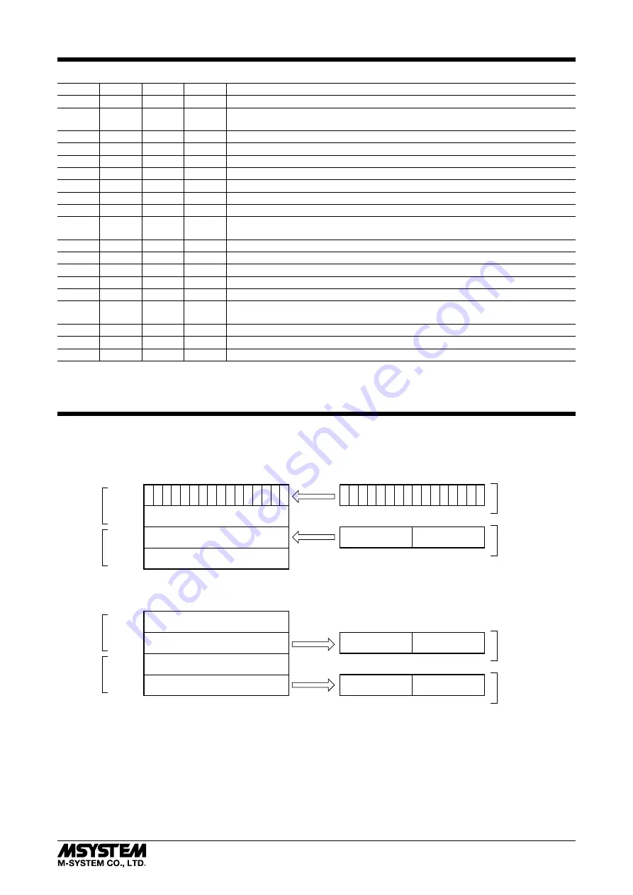
STATUS INDICATOR LED
RUNx
ERRx
SDx
*
1
RDx
STATUS
*
2
ON
BL
BL
ON
Communicates normally with occasional CRC errors due to noise interference.
ON
BL
BL
ON
Communicates normally but the Baud Rate and/or Station Address switches failed.
ERRx LED blinks approximately in 0.5 seconds intervals.
ON
BL
BL
OFF
----
ON
BL
OFF
ON
CRC error found in the received data. Unable to respond.
ON
BL
OFF
OFF
----
ON
OFF
BL
ON
Normal communication
ON
OFF
BL
OFF
----
ON
OFF
OFF
ON
Unable to receive data addressed to the station.
ON
OFF
OFF
OFF
----
OFF
BL
BL
ON
Performs the interval-timed responses but CRC error found in receiving the refresh
data.
OFF
BL
BL
OFF
----
OFF
BL
OFF
ON
CRC error found in the data addressed to the station.
OFF
BL
OFF
OFF
----
OFF
OFF
BL
ON
Link is not started.
OFF
OFF
BL
OFF
----
OFF
OFF
OFF
ON
No data addressed to the station. Or unable to receive data addressed to the station
due to noise interference. (Missing parts of the data sent from the master)
OFF
OFF
OFF
OFF
Unable to receive data due to wire breakdown
OFF
ON
OFF
ON/OFF Faulty Baud Rate and/or Station Address setting
OFF
OFF
OFF
OFF
Power input removed. Or power supply failure.
OFF = OFF, ON = ON, BL = Blinking
*1. SDx LED may look not blinking but ON with high baud rate and fewer connected modules.
*2. LEDs indicated with “----” in STATUS rarely occurs in normal operation (LED failure or the like as possible cause).
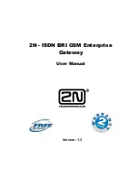
DATA ALLOCATION
0
1
2
3
4
5
6
7
8
9
A
B
C
D
E
F
0
1
2
3
4
5
6
7
8
9
A
B
C
D
E
F
RX(n+1)
RX(n+0)
CH1
CH2
CH1
CH2
RX(n+2)
RX(n+3)
Interval-timed Response(X)
CC-Link
Do
HLS
Unused
Unused
{(80+2m) +1}H
{(80+2m) +0}H
{(80+2m) +3}H
{(80+2m) +2}H
0
1
2
3
4
5
6
7
8
9
A
B
C
D
E
F
0
1
2
3
4
5
6
7
8
9
A
B
C
D
E
F
RY(n+1)
RY(n+0)
n: CC-Link station address selected with rotary SW.
m: HLS module address selected with rotary SW.
CH1
CH2
CH1
CH2
RY(n+2)
RY(n+3)
Refresh Data(Y)
Di
Unused
Unused
{(100+2m) +1}H
{(100+2m) +0}H
{(100+2m) +3}H
{(100+2m) +2}H


