background image

58

SC100/200 Series Function Block Application Manual  EM-6460-C

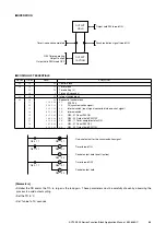
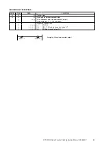
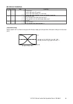
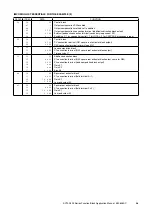
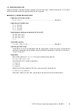
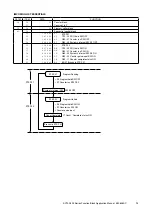
 CODING LIST ESSENTIALS FOR THE EXAMPLE (2)

GROUP

ITEM

DATA

FUNCTION

02

10
47
48
49
56
58

2 2

1
1

3 1 2 1
0 3 2 2
0 ,   1

Control block
Output compensation SW enabled
Output compensation method set to ‘addition’
Output compensation connection terminal (addition/subtraction block output)
External feedback connection terminal (secondary loop current SP)
Switching 0 / 1 by sequential control (‘1’ for LOCAL, ‘0’ for CASCADE at secondary loop)

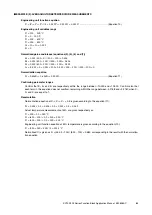
03

10
15
24

2 2

4 1 2 1
0 2 2 5

Control block
PV connection terminal (G41 square root extractor block output)
CAS connection terminal (primary loop MV)

30

10
11
12

6 5

4 0 2 1

s e t

Lead computation block
X1 connection terminal (G40 square root extractor block output)
Time constant T

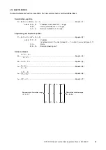
31

10
11
12
14
15
17

5 1

4 0 2 1
3 0 2 1

s e t
s e t

0 . 0 0 0

Addition/subtraction block
X1 connection terminal (G40 square root extractor block output, same for G30)
X2 connection terminal (lead computation block output)
Gain K1
Gain K2
Bias A0

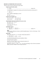
40

10
11
12
13

5 4

0 4 2 3

1 0 . 0 0 0

3 . 0 0 0

Square root extractor block
X1 connection terminal (field terminal Ai 1)
Gain K1
Low-end cutout A1

41

10
11
12
13

5 4

0 4 2 2

1 0 . 0 0 0

3 . 0 0 0

Square root extractor block
X1 connection terminal (field terminal Pv 2)
Gain K1
Low-end cutout A1

Summary of Contents for SC100 Series

Page 1: ...1 SC100 200 Series Function Block Application Manual EM 6460 C SC100 200 Series MULTI FUNCTION PID CONTROLLER FUNCTION BLOCK APPLICATION MANUAL...

Page 2: ...ION TERMINALS SC200 210 13 3 1 DI RECEIVE TERMINAL 13 3 2 DO SEND TERMINAL 13 3 3 AI RECEIVE TERMINAL 13 3 4 AO SEND TERMINAL 13 4 CONTROL BLOCKS 14 4 1 CONTROL BLOCK TYPES 14 4 1 1 SIMPLE LOOP CONTRO...

Page 3: ...ROCESS GAIN CHANGE 53 4 3 17 FEEDFORWARD CONTROL ADDITION SUBTRACTION 55 4 3 18 FEEDFORWARD CONTROL MULTIPLICATION DIVISION 59 5 COMPUTATIONAL FUNCTION BLOCKS 60 5 1 MATH FUNCTIONS 60 5 1 1 NORMALIZAT...

Page 4: ...LOCKS 85 6 1 2 SEQUENTIAL CONTROL COMMANDS 86 6 2 RELAY SEQUENCE 90 6 2 1 GENERAL DESCRIPTIONS 90 6 2 2 LADDER COMMAND DESCRIPTIONS 91 6 2 3 FREQUENTLY USED CIRCUIT CONFIGURATIONS 93 6 3 STEP SEQUENCE...

Page 5: ...iscrete pulse input with excitation supply 1 point Analog MV output 2 points 4 20 mA DC Analog voltage output 2 points 1 5 V DC Discrete output 5 points Software communication terminals 16 blocks SC20...

Page 6: ...other in the programming just like physical wiring No specialized programming skill is required The figure below shows an example describing combined analog and sequential control functions realized...

Page 7: ...gistered at the destination function block where the signal is taken in and used A terminal is described as GGNN where GG means Group No and NN means Terminal No G04 Field Terminal Block 21 G30 Square...

Page 8: ...s 12 blocks x 89 commands can be registered C C G G N N Terminal No Group No Command Code Major commands 01 INPUT The first N O contact in a relay circuit 03 AND N O contact in series to INPUT 05 OR N...

Page 9: ...al 1 Group 04 Set temperature range to 0 0 80 0 C with ITEM 82 upper range set to 800 ITEM 83 lower range set to 0 and ITEM 84 decimal point position set to 1 Set reverse control action with ITEM 40 s...

Page 10: ...1 SM 0 Setting mode 0 local 1 cascade local DEVIATION 34 0 00 115 00 DL 115 00 Deviation alarm setpoint hysteresis deadband in ITEM 21 CONTROL 40 0 1 DR 1 Control direction 0 direct 1 reverse MV decre...

Page 11: ...in at once are set at Field Terminal blocks I O signals through Communication Terminal blocks are handled according to the NestBus transmission procedure Computation functions are processed in the or...

Page 12: ...rs at a specific point of control sequence Register parameters at Parameter Setter function block and send them to a specified block by a sequential control command Available parameters depend upon ea...

Page 13: ...to receive 32 point discrete signals from an external remote I O or controller module Identifying the sender ITEM 11 Sender Station No Set always to FF ITEM 12 Sender Card No ITEM 13 Sender Group No...

Page 14: ...2 and 03 to realize two independent PID control loops In the following example Group 02 and Group 03 MV outputs are provided via respective MV output terminals of the Controller If PID is not needed M...

Page 15: ...Manual EM 6460 C 4 1 3 CASCADE CONTROL PID control function is applied to Group 02 and 03 and the primary loop MV output is connected to the secondary loop SP input in the example shown PID G02 PV MV...

Page 16: ...inal is not needed Setting mode ITEM 29 Used to specify whether the setpoint value is controlled only locally Loc mode or its setting should be able to be switched between cascade and local control Ca...

Page 17: ...pensation SW Terminal 06 ITEM 37 The input compensation is applied in the method specified with ITEM 38 when the switch is turned on Use the terminal 06 to control it from a sequential control block I...

Page 18: ...trol valve action and control direction CONTROL LOOP VALVE LOCATION CONTROL OBJECT CONTROL DIRECTION DIRECT ACTION VALVE REVERSE ACTION VALVE Temperature control Heating Cooling Direct Reverse Reverse...

Page 19: ...rol it from a sequential control block Output compensation method ITEM 48 0 Without compensation 1 Addition An external signal is added to the PID output 2 Subtraction An external signal is subtracted...

Page 20: ...to control it from a sequential control block 4 2 10 EXTERNAL FEEDBACK OUTPUT TRACKING Advanced PID External feedback signal is routed to the PID control output output tracking when the switch is tur...

Page 21: ...ring a cascade control system is to eliminate through use of a secondary controller the influ ence of disturbance on the primary loop which enters through the secondary control loop LOOP CONFIGURATION...

Page 22: ...e C L SW status signal to directly control the external feedback SW without needing a sequential control block CODING LIST ESSENTIALS FOR THE EXAMPLE 1 GROUP ITEM DATA FUNCTION 02 10 56 2 2 0 3 2 2 Pr...

Page 23: ...ithout a bump Manual mode Manual control of the valve is available Turn Loc to Cas before turning to Auto mode CODING LIST ESSENTIALS FOR THE EXAMPLE 2 GROUP ITEM DATA FUNCTION 02 10 56 2 2 0 4 2 2 Pr...

Page 24: ...CODING LIST ESSENTIALS GROUP ITEM DATA FUNCTION 02 10 2 4 Primary loop control block ratio setter 03 10 24 2 1 0 2 2 5 Secondary loop control block PID CAS connection terminal primary loop MV 81 10 9...

Page 25: ...OGRAM CONTROL Setpoint is provided as a preset ramp program running over time LOOP CONFIGURATION EXAMPLE BLOCK DIAGRAM steam temp PV TIC MV L Complete SW Program Setter SP temp PV SP TIC G02 preset va...

Page 26: ...ST OF ON OF OF IN STEP 01 program reset DO contact Program Complete lamp OFF Preset value selector SW set to Preset C L SW set to Local Program Run SW OFF SW ON 17 18 19 20 21 1 3 0 0 0 2 1 0 0 2 0 8...

Page 27: ...Control output at preset value 0 Program Run SW OFF STEP 02 Final Phase Program Running Final phase reached Control output at AUTO mode preset SW OFF Program Run SW ON STEP 03 SW Program Complete OFF...

Page 28: ...of external feedback output tracking function LOOP CONFIGURATION EXAMPLE Temperature control of a tank is the main purpose of the system The FIC is used to maintain steam flow within a preset limit Th...

Page 29: ...steresis deadband 31 10 11 5 5 0 2 2 3 Absolute value block X1 connection terminal deviation output from the primary loop 32 10 11 5 5 0 3 2 3 Absolute value block X1 connection terminal deviation out...

Page 30: ...rs when the integral term accumulates a significant error during initial temperature rise in a batch control system windup LOOP CONFIGURATION EXAMPLE Heating control of a batch reactor is given as an...

Page 31: ...the secondary loop is switched to Cas mode reactor hot water tank PV PV external feedback deviation TIC G03 TIC G02 MV A M SP MV CTS G31 SEQ G81 PVA G30 PMS G32 PMS Parameter Selector High Low Alarm P...

Page 32: ...ck TI G3 connection terminal to the primary control block TD A1 parameter PB A2 parameter TI A3 parameter TD 81 10 9 5 Sequential control block 11 12 13 14 15 16 17 18 19 20 1 3 0 0 0 0 0 1 8 0 0 3 0...

Page 33: ...nimizing the initial heating time and avoiding an excess overshooting caused by accumulated integral term It is used also because of the relative simplicity in determining the deviation set value LOOP...

Page 34: ...rameter Selector High Low Alarm Sequence G30 deviation 1 1 G02 Control block primary loop G03 Control block secondary loop G30 High Low Alarm to detect deviation G31 Input Selector G32 Parameter Selec...

Page 35: ...r selector block A1 parameter output 1 A2 parameter output 2 81 10 9 5 Sequential control block 11 12 13 14 15 16 17 18 19 20 1 3 0 0 0 0 0 1 8 0 0 3 0 7 0 2 1 1 0 2 0 3 0 3 0 6 3 0 1 1 0 7 0 2 1 0 0...

Page 36: ...ocess control LOOP CONFIGURATION EXAMPLE NEUTRALIZATION CONTROL The titration curve around pH 7 with an extreme non linearity is adjusted to provide a relatively constant gain over entire span by decr...

Page 37: ...ar gain block output 30 10 11 12 13 14 15 5 6 0 2 2 3 1 0 0 0 s e t 1 0 0 0 s e t Non linear gain deadband block X1 connection terminal deviation output for input compensation Gain K1 Non linear gain...

Page 38: ...position while in this range OPERATION CODING LIST ESSENTIALS GROUP ITEM DATA FUNCTION 02 10 37 38 39 2 2 1 3 3 0 2 1 Control block Input compensation SW enabled Input compensation method set to subs...

Page 39: ...he deviation SP PV equals 0 in a proportional control system is called manual reset value In the above process the tank level stays at a constant value when the outflow equals the inflow The deviation...

Page 40: ...6460 C BLOCK DIAGRAM CODING LIST ESSENTIALS GROUP ITEM DATA FUNCTION 02 10 42 43 44 64 2 2 s e t 0 0 0 0 0 0 s e t Control block Proportional band Integral time 0 00 no integral Derivative time 0 00...

Page 41: ...block is applied to each zone The high low setpoints should be provided with a deadband to avoid cycling between parameters Caution of using Parameter Setter block Parameters in each function block ca...

Page 42: ...lied between the alarm setpoints TI set value applied between the alarm setpoints TD set value applied between the alarm setpoints 33 10 11 12 13 14 15 16 7 9 0 2 4 2 0 2 4 3 0 2 4 4 s e t s e t s e t...

Page 43: ...ignal is turned on and then the MV signal is held Since the hold function is cancelled after a new PV is given and stabilized bumpless output tracking cancels changes in the pro portional term MV outp...

Page 44: ...hot signal Internal switch G30 01 Count SW ON G02 09 Output hold SW OFF G30 11 Timer complete status ON G30 01 Count SW OFF G02 09 Output hold SW ON Parameters Smaller the PB and or the TI t1 is large...

Page 45: ...to a step input The dead time L could cause hunting problem when simple PID control is applied but it can be avoided by adding the dead time compensation block that is used to subtract a calculated co...

Page 46: ...tant TC Sampling cycle H Number of samples to be calculated N dead time H x N 31 10 11 14 5 1 3 0 2 1 s e t Addition subtraction block X1 connection terminal dead time compensation block output Gain K...

Page 47: ...PV PV PV MV LS M Example 1 Temperature control water level LC LIC Example 3 Maintaining the minimum liquid level in a tank Example 2 Interlocking to prevent idle running of an agitator feed evaporator...

Page 48: ...S FOR THE EXAMPLE 1 GROUP ITEM DATA FUNCTION 30 10 11 12 13 14 7 6 0 4 2 1 s e t s e t s e t High low alarm block X1 connection terminal field terminal PV High setpoint A1 Low setpoint A2 Deadband A3...

Page 49: ...PERATION Analog pulse duration converter block provides pulse width modulation output status signals in proportion to the analog input signal temp PV TIC constant cycle proportional to the control out...

Page 50: ...0 2 2 5 3 0 Analog pulse duration converter block X1 connection terminal control block MV output Pulse cycle time CT 0 1000 seconds 81 10 9 5 Sequential control block 11 12 13 1 3 0 0 0 0 0 1 3 0 1 1...

Page 51: ...linear characteristics Linearizer block is used to compensate such changes BLOCK DIAGRAM TIC PRI PV MV FIC SEC PV SP MV primary loop secondary loop function f x Loop gain change could occur in the sec...

Page 52: ...inearization Data 1 Manually operate the valve to determine a valve characteristics curve that correlates valve position and flow 2 Divide the valve position axis into eight 8 divisions do not need to...

Page 53: ...in the gain to a constant level LOOP CONFIGURATION EXAMPLE BLOWER OUTFLOW CONTROL Loop gain changes with the blower outflow due to its revolution speed change The revolution speed signal is supplied t...

Page 54: ...7 2 2 1 0 2 2 3 1 0 0 0 Multiplication block X1 connection terminal linearizer block output X2 connection terminal control block deviation output Gain K1 72 10 11 5 8 0 4 2 3 Linearizer block X1 conne...

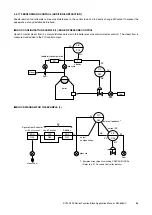
Page 55: ...sturbance factor in the boiler pressure control master control The steam flow is measured and added to the PIC control output BLOCK DIAGRAM FOR THE EXAMPLE 1 fuel steam FIC SEC PIC PRI PV X1 X0 PV MV...

Page 56: ...pensation connection terminal addition subtraction block output 03 10 24 2 2 0 2 2 5 Control block CAS connection terminal primary loop MV 30 10 11 12 6 5 0 4 2 3 s e t Lead computation block X1 conne...

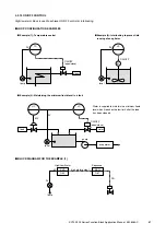
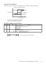
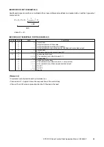
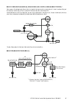
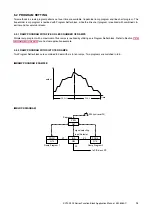
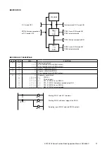
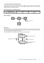
Page 57: ...and added to the feed water setpoint feedforward control Involves three elements drum level feed water flow and main steam flow BLOCK DIAGRAM FOR THE EXAMPLE 2 water main steam LIC PRI PV X1 X0 PV MV...

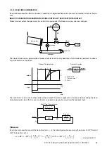
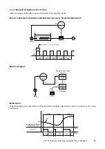
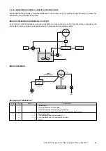
Page 58: ...terminal G41 square root extractor block output CAS connection terminal primary loop MV 30 10 11 12 6 5 4 0 2 1 s e t Lead computation block X1 connection terminal G40 square root extractor block out...

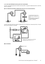
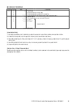
Page 59: ...y the PHC output Same principle can be applied with a FIC loop instead of the metering pump BLOCK DIAGRAM CODING LIST ESSENTIALS GROUP ITEM DATA FUNCTION 02 10 47 48 49 2 2 1 3 3 0 2 1 Control block O...

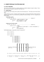
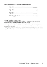
Page 60: ...where X0 X1 X2 X3 Variables normalized to 0 1 range K1 K2 K3 Gains normalized to 0 1 range A0 Bias normalized to 0 1 range Engineering unit function equation Y0 G1Y1 G2Y2 G3Y3 B0 Equation 2 where Y0...

Page 61: ...into one with each term corresponding the normalization equation 2 Determine 0 and 100 engineering unit values for each of inputs and outputs 3 Formulate a normalization equation Calculate gains K0 K...

Page 62: ...0 250 K3 300 400 0 750 A0 0 Normalization equation X0 0 5X1 0 25X2 0 75X3 Equation 9 Confirming parameter ranges Confirm that K1 K2 and K3 are respectively within the range between 10 000 and 10 000 C...

Page 63: ...onfirming parameter ranges Confirm that K1 K2 and K3 are respectively within the range between 10 000 and 10 000 Confirm also that each term in the equation does not overflow remaining within the rang...

Page 64: ...and 7 K1 1 5 1 0 1 5 1 0 1 K2 0 0012 100 0 1 5 1 0 0 24 A0 1 0 0012 0 0 06 1 1 1 5 1 0 0 12 Normalization equation X0 X1 0 24X2 0 12 Equation 13 Confirming parameter ranges Confirm that K1 and K2 are...

Page 65: ...range A0 A1 A2 Bias normalized to 0 1 range Engineering unit function equation Y0 G1Y1 B1 G2Y2 B2 B0 Equation 2 where Y0 Y1 Y2 Variables engineering unit Yn varies between Yn0 Yn1 when Xn varies betw...

Page 66: ...ormalized gains and biases equations 3 4 5 6 and 7 K1 1200 2000 0 6 K2 4 A0 A1 A2 0 Normalization equation X0 0 6X1 4X2 Equation 9 Recalculation Normalization equation at X1 X2 0 5 is given according...

Page 67: ...A0 A1 A2 Bias normalized to 0 1 range Engineering unit function equation G1Y1 B1 Y0 B0 Equation 2 G2Y2 B2 where Y0 Y1 Y2 Variables engineering unit Yn varies between Yn0 Yn1 when Xn varies between 0...

Page 68: ...7 K1 40 0 5 80 K2 60 A0 A1 A2 0 Normalization equation X0 80X1 60X2 4X1 3X2 Equation 9 Note Reduce fractions so that gains and biases are within the selectable ranges 10 000 to 10 000 for gains 1 1500...

Page 69: ...1 5 1 0 60 K2 100 50 50 A0 1 0 1 5 1 0 2 A1 50 10 1 5 1 0 120 A2 50 20 30 Normalization equation 60X1 120 0 6X1 1 2 X0 2 2 Equation 11 50X2 30 0 5X2 0 3 Note Reduce fractions so that gains and biases...

Page 70: ...PROGRAM WITH FIVE OR LESS NUMBER OF RAMPS Simple ramp program with a maximum of five ramps is realized by utilizing one Program Setter block Refer to Section 4 3 3 PROGRAM CONTROL for an actual appli...

Page 71: ...0 1 0 5 1 1 0 7 7 2 0 1 0 1 7 2 1 1 0 7 7 3 0 1 0 7 3 2 0 1 ST IN OT IN OT OT STEP 00 DI start signal G72 01 PRG 1 to run SW ON G72 11 PRG 1 final phase reached output ON G73 01 PRG 2 to run SW ON G32...

Page 72: ...r 1 second OFF for 99 seconds Tn x 10 Tn x 100 Kn x 0 1 Kn x 0 01 BLOCK DIAGRAM OPERATION Clock cycle of Timer block is not synchronized with the Controller s computation cycle Counter block is used i...

Page 73: ...W S5 OFF 15 16 17 18 19 20 21 1 3 0 0 0 2 0 9 7 2 0 2 0 9 3 0 0 1 0 1 8 0 0 5 0 7 3 0 0 2 0 1 3 0 1 1 1 2 0 0 0 1 ST ON ON IN OT IN BR STEP 02 G72 02 PRG hold SW ON G30 01 Counter run SW ON G80 05 Sys...

Page 74: ...ter block PRG 1 73 10 6 9 Program setter block PRG 2 74 10 6 9 Program setter block PRG 3 81 10 9 5 Sequential control block 11 12 13 14 15 16 17 1 3 0 0 0 0 0 1 0 5 1 1 0 7 3 0 0 1 0 1 0 5 1 2 0 7 3...

Page 75: ...ate in the accumulator block or the full scale time parameter in the parameter selector block 2 Each time index corresponds to one output value No need of calculating ramp rates 3 No limitation in ram...

Page 76: ...X1 connection terminal accumulator output 81 10 9 5 Sequential control block 11 12 13 14 15 1 3 0 0 0 0 0 1 3 0 0 1 0 8 3 2 0 2 0 1 3 2 1 1 0 7 3 2 0 1 ST IN NO IN OT STEP 00 DI field terminal turned...

Page 77: ...set automati cally after the count has reached 10000 until the reset SW S1 is turned on Turn on the interrupt SW S2 in order to halt counting Accumulated value output is provided at Q0 COUNTER RATE Co...

Page 78: ...Accumulator block Preset value 31 10 9 2 Counter block 81 10 9 5 Sequential control block 11 12 13 14 15 16 1 3 0 0 0 0 0 1 8 0 0 4 0 8 3 1 0 1 0 1 3 0 1 1 0 7 3 1 0 2 1 1 3 0 0 2 ST IN NO IN OT SH S...

Page 79: ...provided to drive an external counter when the counter is reset by watching the Q0 accumulated value output with High Low Alarm block CODING LIST ESSENTIALS GROUP ITEM DATA FUNCTION 30 10 13 6 8 s e...

Page 80: ...set condition Maximum minimum or momentary value memory is selectable in ITEM 12 Hold mode setting X0 X1 when S1 is at 1 OUTPUT SHOT command in the sequential control block is used to reset INPUT SELE...

Page 81: ...ADS Addition Subtraction STORING THE MAXIMUM RATE OF CHANGE In the above example Maximum Value Selector MAX is used to store positive rate of change Choose Minimum Value Selector MIN to store negative...

Page 82: ...EXAMPLE The valve opens by Start signal and closes when deviation extracted volume alarm trips BLOCK DIAGRAM OPERATION level LCQ blowdown valve feed command feed command DI DO AI X1 X1 Y1 X2 X2 X0 SE...

Page 83: ...0 0 1 1 0 3 0 0 1 1 0 0 5 0 1 0 1 0 5 1 1 ST OF OF IN STEP 01 G30 01 Input selector measured output DO Valve closed DI Feed command ON 15 16 1 3 0 0 0 2 0 9 3 0 0 1 ST ON STEP 02 G30 01 Input selecto...

Page 84: ...0 0 0 0 0 1 3 0 0 1 0 5 0 5 0 1 0 4 3 0 0 2 0 4 3 1 1 1 0 7 0 5 0 1 0 8 3 1 0 2 ST IN OR NA NA OT NO STEP 00 DI 1 Start PBS pressed DO Hold by feed output DI 2 Valve close command when reset command P...

Page 85: ...realize a series of sequence commands A specific step in one block can be launched by a command from another block COMMANDS TO CONTROL THE BLOCK S1 Run SW With S1 turned on Steps 00 and 01 start opera...

Page 86: ...ition is true when the contact X in the ladder diagram to the left is turned off or at 0 and the output 1 is provided 0 2 G G N N Command X terminal No INPUT NOT CODE 03 AND Abbr AD A N O contact conn...

Page 87: ...vice that operates in this manner 0 8 G G N N Command Y terminal No OUTPUT NOT OUTPUT Y Y OUTPUT NOT Y Y CODE 05 OR Abbr OR A N O contact connected in parallel with the first contact in a row Conditio...

Page 88: ...Command Y terminal No OUTPUT ON CODE 10 OUTPUT OFF Abbr OF A reset coil in a latching relay circuit The contact Y is turned off or at 0 when the circuit is closed 1 0 G G N N Command Y terminal No OUT...

Page 89: ...timer does not automatically prompt the program operation to the next step The timer output Y1 is turned on when the set time has been elapsed Use the Y1 to handle any error procedure in a sequential...

Page 90: ...command only in a next cycle 2 If one switching device is operated multiple times in one cycle operation result at the most downstream block prevails 3 One contact or coil can be used multiple times...

Page 91: ...3 AND X4 AND NOT X5 OUTPUT Y X1 X2 X3 X4 X5 Y OR NOT INPUT X1 OR NOT X2 OR X3 OR X4 OR NOT X5 OUTPUT Y X Y1 Y2 Y3 Y4 Y5 MULTIPLE OUTPUTS INPUT X OUTPUT Y1 OUTPUT Y2 OUTPUT NOT Y3 OUTPUT SHOT Y4 OUTPUT...

Page 92: ...3 AND X4 OR 0000 OUTPUT Y Two AND circuits are connected via OR command without input INPUT X1 AND X2 OUTPUT y1 INPUT X3 AND X4 OUTPUT y2 INPUT y1 OR y2 OUTPUT Y The following command description usin...

Page 93: ...y3 1 sec ON 0 5 sec OFF or 0 5 sec ON 1 sec OFF with 0 5 sec computation cycle INPUT y2 OUTPUT y1 INPUT y3 AND NOT y1 OUTPUT y2 INPUT NOT y1 OUTPUT y3 y2 y2 y2 y1 y3 y3 y1 1 2 OPERATION Output y1 turn...

Page 94: ...y2 INPUT y2 OR Y AND NOT y1 OUTPUT Y y2 Y X y2 X Y Y y2 y1 OPERATION With contact X turned on one shot output y2 is provided to latch contact Y With contact X turned off and on again contact Y is on a...

Page 95: ...ains on until a next OFF command is received OUTPUT OFF Once turned off the output remains off until a next ON command is received BRANCH Activates a specified step in a specified block STEP Declares...

Page 96: ...MER 0 100 setting at 100 seconds YES STEP 02 STEP 02 Moving to the next step when the step timer is completed Step timer completed STEP 01 STEP 01 OUTPUT Y1 ON STEP 02 STEP 02 Moving to the next step...

Page 97: ...YES NO STEP 02 STEP 02 CONDITION X1 OUTPUT Y1 ON OUTPUT Y1 ON STEP 01 Moving to the next step after the previous step has provided output when the condition was valid STEP 01 OUTPUT Y1 ON YES NO STEP...

Page 98: ...CONDITION X3 OUTPUT Y1 ON OUTPUT Y1 ON INPUT X1 CONDITION X1 OUTPUT Y2 ON OUTPUT Y2 ON STEP 02 STEP 02 NO NO TIMER 0 100 setting at 100 seconds NO Operating the output that needs to be always ON or OF...

Page 99: ...ng when the S1 is turned on The Y1 is turned on when the preset time has been elapsed When the S1 is turned off the Y1 is also reset to off The S2 always remains off WITH COUNT INTERRUPTION Turn on th...

Page 100: ...tput count complete ON DELAY TIMER Output is turned on in a certain time period after the run command is turned on S1 X1 Y Y1 INPUT X1 Run command OUTPUT S1 Count SW INPUT Y1 Reset SW OUTPUT Y Delay o...

Page 101: ...set time set to 0 5 second The timer function block must be assigned to a smaller group number than that for the sequential control block Time counting is interrupted while the interrupt command X2 is...

Page 102: ...s 0 5 s T2 T1 T2 DOUBLE TIMERS T1 S1 X T2 S1 T1 Y1 INPUT X Run command AND NOT T2 Y1 T2 complete output OUTPUT T1 S1 T1 run SW INPUT T1 Y1 T1 complete output AND NOT T2 Y1 T2 complete output OUTPUT T2...

Page 103: ...ective product 2 replace the defective product or 3 refund the purchase price for the defective product paid by the purchaser Except as otherwise provided by applicable state law these remedies consti...

Reviews: