Energy Butler Hybrid Series
User Manual
37
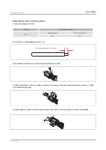
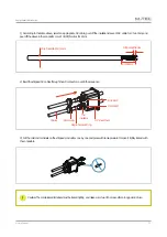
7) Screw up the rubber ring and anti-water cap to make sure the AC connector is well sealed.
Grid
Normal
Loads
RCD
RCD
Back-up
Loads
Communication
Communication
BACK-UP
The additional
grounding hole
ON-GRID
PV1+
Breaker
E-BAR
N-BAR
Breaker
RJ45
1(L1)
5(L1
-S1)
12(L)
9(L3-S1)
10(L3-S2)
2(L2)
6(L1
-S2)
3(L3)
7(L2-S1)
4(N)
8(L2-S2)
13(N)
Breaker
Main Switch/Breaker
CT
CT-1
CT-2
CT-3
Switch/Breaker
L1
L1
L2
L2
L3
L3
N
N
PV2+
PV1-
PV2-
RJ45-BMS
RJ45-Meter
B+
B-
M-TEC
Hybrid
Inverter
Meter
House
→
Grid
Attention: CT installation direction and phase sequence should strictly follow the instruction in the user manual, otherwise,
the inverter may not be working normally.
Attention: The CT has to be corresponding with the port in the meter, and the connection between CT and Meter needs to
be reliable, otherwise, the CT measurement accuracy may be affected.
Note: The rated current of CT in the inverter accessory box is 80A, and the maximum allowed inserted cable diameter
is 16mm. If the max current through the CT exceeds the rated current or the cable diameter wider than 16mm, please
contact M-TEC for help.
Meter and CT connection
1) The current transducer, also called CT, is usually installed on the fire wires between the house loads and the power grid.
The Meter can install in the AC combiner box or other places that are unable to be touched by children. M-TEC CT integrated a
cable with length of 2m and could be extended to 5m at max.


