background image

MT-500

27

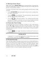
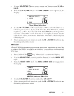
TIME/DATE 

or 

SOG/COG

.  

MANUAL LL 

is described separately.

Push the 

SELECT/ENT

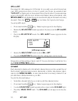
 knob.  The On/Off option is displayed.

Use the 

SELECT/ENT 

knob or any microphone key to select either On or

Off.

Push the 

SELECT/ENT

 knob to store the selection and exit to the previ-

ous menu.

The 

MANUAL LL 

data item has 3 options, On/Off/Set.  The Set option is used

to manually enter your approximate Lat/Lon position and time of day for
distress messages if your GPS is not connected or not functioning.  If Manual
Lat/Lon is turned On, it overrides your GPS Lat/Lon position.  Be sure Manual
Lat/Lon and time of day are correctly entered before turning the function On.
Time of day is entered as your local time in either 12 hour or 24 hour format.
Its is important that your local time offset from Universal Coordinated Time
(UTC) is set correctly.  See the 

TIME SET 

topic on the Main Menu.

To set Manual Lat/Lon:

Press and hold the 

CALL

 key.  Menu topics appear in the display.

Use the 

SELECT/ENT 

knob to position the cursor on the 

DATA SET 

topic.

Push the 

SELECT/ENT

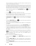
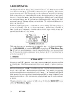
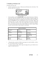
 knob.  The Data Set menu selections appear in the

display.

USA

INT

LLPOSITION

TIME/DATE

SOG/COG

MANUAL LL

Data Set Selections

Use the 

SELECT/ENT 

knob or 

ENT

 or 

EXIT

 to select 

MANUAL LL

.

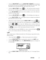
Push the 

SELECT/ENT

 knob.  The 

MANUAL LL


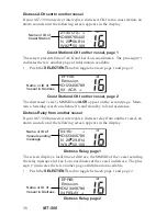
menu appears in the

display.

INT

MANUAL LL

ON

OFF

>SET

Manual LL Menu

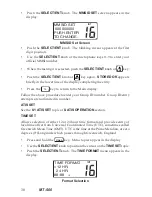
Use the 

SELECT/ENT 

knob to select 

SET

 on the menu.

Summary of Contents for MT-500

Page 1: ...OWNER S HANDBOOK MT 500 VOL S Q OFF INT MT 500 16 H L SCAN MENU MEM CALL END P USH EN T E R P U S H E N T E R DISTRESS...

Page 2: ...TSI EN 301 698 3 V1 1 1 2001 05 All essential radio test suites have been carried out NOTIFIED BODY EMCCert Dr Rasek Address Boelwiese 5 91320 Ebermannstadt Germany Identification Number 0678 MANUFACT...

Page 3: ...o gener ates and radiates radio frequency RF electromagnetic energy EME This equipment must be installed and operated in accordance with the instructions contained in this handbook Failure to do so ca...

Page 4: ...1 Transceiver 11 4 2 Antenna 11 4 3 Power Connection 11 4 4 NMEA Cable 12 4 5 External Speaker Connection 12 4 6 Rear Panel Connectors 12 4 7 Antenna Connector 12 5 OPERATION 13 5 1 General 13 5 2 Dis...

Page 5: ...39 Individual DSC Call 39 Directory Call 39 Manual Call 41 All Ships Call 43 Group Call 44 Position Send 45 Position Request 46 7 5 Receiving DSC Calls 47 Individual Call Received 48 Last Call Receive...

Page 6: ...r ence to marine electronic equipment which can be determined by turning this radio Off and On the user is encouraged to try to correct the interference by one or more of the following measures Reorie...

Page 7: ...ional Coast Guards and other search and rescue SAR agencies use this information to help speed search and rescue opera tions 2 2 Required License Information The following information pertaining to yo...

Page 8: ...MT 500 7 2 4 Equipment Supplied MT 500 Marine VHF Transceiver Microphone with alphanumeric keypad Mounting Bracket with knobs Power Cable with in line fuse 6 3 Amp NMEA Data Cable Flush Mounting Kit...

Page 9: ...ute 1 Press the microphone Push To Talk button Speak slowly and clearly into the microphone Mayday Mayday Mayday this is your vessel s name your vessel s name your vessel s name 2 Then repeat once May...

Page 10: ...isten for traffic If necessary wait for traffic to clear and then call the other vessel As communication proceeds end each transmission with over When communication with the other vessel is completed...

Page 11: ...in addi tion to any other charges associated with the call 3 4 Prohibited Communication The following communications are prohibited by regulations and violators are subject to penalties False distress...

Page 12: ...be located as high as practical and separated as much as possible from other antennas and structures The minimum distance to other objects is 1 meter Route the an tenna cable away from other electron...

Page 13: ...er Your GPS must output the GPRMC GGA NMEA data sentence Refer to your navigation receiver manual for information about its NMEA output settings and connections 4 5 External Speaker Connection Provisi...

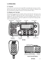
Page 14: ...the current operating status menus for selecting functions and set tings for optional features The microphone has a keypad for changing chan nels and selecting functions MT 500 USA INT CAN Frequency...

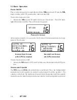
Page 15: ...reen ap pears in the display INT 16 PRI HI MEM CHANNEL N 28 04 814 W 83 42 169 INT 16 PRI HI MEM CHANNEL 99 99 999 999 99 999 Normal Com Screen Normal Com Screen with GPS Connected w o GPS connected T...

Page 16: ...press and hold the ENT or EXIT keys or directly enter the channel number using the numeric keys on the microphone The ENT and EXIT keys will always change channels except when being used to enter or e...

Page 17: ...CanbeusedaloneorwiththeMEM keytoselectPriorityScan Memory Scan or All Scan MEM Stores channels in the scan memory bank and when used with the SCAN key starts Memory Scan END Cancels DSC calls and Eme...

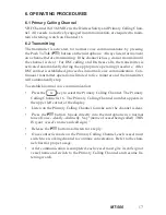
Page 18: ...ansmitter operation is limited to five minutes and the transmitter will automatically stop To establish normal voice communication Press the 16 key to select the Primary Calling Channel The Primary Ca...

Page 19: ...tings 25 watts or 1 watt which are indi cated by HI or LO appearing in the upper line of the display The normal power setting is HI for all channels where 25 watts is allowed Use the 1 watt setting fo...

Page 20: ...Digital Selective Calling DSC channel Voice traffic is not permitted on this channel If noisy or busy channels interfere with scanning the interfer ing channels may be temporarily removed from the sc...

Page 21: ...ess the MEM key again to advance to the next page of channels The memory channel bank can hold all usable voice communication channels INT INT INT Memory Scan Bank Memory Scan Bank Memory Scan Bank De...

Page 22: ...s the MEM key The Memory Scan channel bank appears in the display Press the SCAN key MSCAN appears in the upper line of the display The scanned channel numbers appear in sequence in the channel num be...

Page 23: ...next higher menu level To exit the menus and return to communication functions Press the 16 key If the SELECT ENT knob was not pushed to store a new value no changes are made 6 7 Main Menu Topics DIR...

Page 24: ...knob Only numbers are allowed in the ID field The following table shows the characters that may be entered in the name field using the microphone keys s y e K e n o h p o r c i M 0 1 C B A 2 F E D 3 I...

Page 25: ...ENT key to move the cursor to the first digit position in the MMSID line Enter the first number in the MMSID Only numbers 0 9 are allowed in theMMSID Press the next microphone number key or push the...

Page 26: ...SELECT ENT knob or the ENT key If more characters in the same line need changing use the SELECT ENT knob or ENT or EXIT key to move the blinking cursor to the next desired character If no more change...

Page 27: ...ELECT ENT knob or microphone keys 0 7 to change the set ting Press the SELECT ENT knob or press and hold the CALL key to store the setting and exit DATA SET Provides On Off control for display of Lat...

Page 28: ...are correctly entered before turning the function On Time of day is entered as your local time in either 12 hour or 24 hour format Its is important that your local time offset from Universal Coordina...

Page 29: ...e blinking cursor on the first character E or W in the Longitude entry line Use the EXIT key to toggle E or W to select a hemisphere East or West designator Push the SELECT ENT knob or ENT to move the...

Page 30: ...ates that Manual Lat Lon is turned On When Manual Lat Lon is turned On the manually entered position overrides any Lat Lon position from a navigation receiver MMSID SET Provides for entry of the 9 dig...

Page 31: ...to the Main display Follow the above procedure to enter your Group ID number Group ID entry attempts are not limited in number ATIS SET See the 8 1 ATIS SET topic of 8 ATIS OPERATION section TIME SET...

Page 32: ...Obtain the time offset value from your GPS navigator When your selection is complete push the SELECT ENT knob to store the setting and exit the menu NMEA SET Allows NMEA sentences from navigation equi...

Page 33: ...ALERT menu appears in the display INT GPS ALERT ON OFF GPS Alert menu Rotate the SELECT ENT knob to select ON or OFF Push the SELECT ENT knob to store the setting and exit the menu NOTE Irrespective o...

Page 34: ...character to the new value When the new value is correct push the SELECT ENT knob or ENT key Up to eleven characters are allowed in the channel name If more charac ters need changing push the SELECT E...

Page 35: ...PRI HI MEM CHANNEL SET GPS DATA NOW Set Manual Lat Lon This warning screen reminds you to manually enter Lat Lon coordinates See the MANUAL LL item of the DATA SET topic of the 6 7 Main Menu Top ics I...

Page 36: ...o reset the countdown timer When the distress is sent the sending distress call screen appears The acoustic alarm goes steady on and remains on until an acknowledg ment is received or the acoustic ala...

Page 37: ...d every 2 minutes to remind you that a distress message is active Unless canceled the distress message is automati cally retransmitted every 3 1 2 to 4 1 2 minutes Re transmissions of DSC distress cal...

Page 38: ...If your MT 500 transceiver intercepts a distress call from another vessel an alarm sounds and the following screen appears in the display INT 20 33 UTC ID323456789 N 28 33 814 W 82 50 169 Name or ID o...

Page 39: ...page 2 The distressed vessel s MMSID and ACK appear on the second page Main tain a listening watch on channel 16 and standby to lend assistance Distress Relay from another vessel If your MT 500 transc...

Page 40: ...or by manually entering the vessel or station MMSID number Position Send and Position Request are made from your directory only Replies to any incoming call type can be made directly from the call lo...

Page 41: ...lect a working channel Even if you select MT 500 ignores it when transmits the call Press the CALL key The INDIVIDUAL call screen appears in the display INT Individual Call Screen Press the CALL key t...

Page 42: ...ng directory However you must know the MMSID for the vessel or station To make a manual DSC call Press the CALL key The DSC calling menu appears in the display Use the SELECT ENT knob to select the IN...

Page 43: ...calls are made on channel 70 If you observe the display closely you will see the channel number change to channel 70 momentarily and then re vert to the selected working channel While waiting for ack...

Page 44: ...SHIP S topic INT LAST CALL DIRECTORY ALL SHIP S INDIVIDUAL DSC All Ship s Call Push the SELECT ENT knob or press the CALL key The CALL TYPE menu appears in the display USA INT CALL TYPE URGENT SAFETY...

Page 45: ...oup MMSID so that any vessel in a group can contact all other vessels in the same group with a single DSC call Your group MMSID is stored in the same manner as your ship MMSID Only one group MMSID is...

Page 46: ...n The Normal Com munication screen appears in the display If there is no response to your call press the END key The Normal Communication screen appears in the display Position Send Positin Send can s...

Page 47: ...request Lat Lon position from another vessel that is listed in your calling directory To make a Position Request Press the CALL key The DSC calling menu appears in the display Use the SELECT ENT knob...

Page 48: ...N appears in the display INT 09 30 UTC vessel name RECEIVED 05 POSITION Position Received Push the SELECT ENT knob to see the received Lat Lon position 7 5 Receiving DSC Calls Your MT 500 can receive...

Page 49: ...pears in the display If the caller is not listed in your directory the caller s MMSID appears in the display Also your transceiver is set to a working channel selected by the caller For Individual Rou...

Page 50: ...ry is lost Making DSC calls from the call log is the like making calls from the DSC calling directory To instantly reply to the last call received or any log entry Press the CALL key The call menu app...

Page 51: ...is not listed in your directory the caller s MMSID appears in the display Also your transceiver is set to Channel 16 by the caller Press the END key to silence the alert sound and listen for a voice a...

Page 52: ...the calling vessel is listed in your DSC calling directory the vessel name as it is listed appears in the display If the caller is not listed in your directory the caller s MMSID appears in the displa...

Page 53: ...ATIS SET SEA WATERWAYS ATIS Set Menu Rotate the SELECT ENT knob to select WATERWAYS to enable ATIS function and automatically disable DSC function Push the SELECT ENT knob to store the setting and ex...

Page 54: ...t Screen Push the SELECT ENT knob The cursor after 9 is blinking The first numeral is always 9 Use the SELECT ENT knob or microphone keys 0 9 to enter the rest of 9 numerals When the last numeral is s...

Page 55: ...ace the antenna and or coaxial cable if damaged in any way or severely weathered Avoid continuous direct sunlight on the LCD Avoid overextending the microphone cable Do not use solvents or harsh chemi...

Page 56: ...MT 500 55 9 3 Troubleshooting...

Page 57: ...nutes into OPEN or SHORT Temperature Range 15 Degrees C to 55 Degrees C Construction UV Stable Case with Backlighted silicon rub ber keypad Die Cast Rear Heat sink LCD Display 4 Lines with 11 characte...

Page 58: ...idual 120 Safety 108 F3E G3E Simplex 100 X Individual 120 Routine 100 F3E G3E Simplex 100 X X Individual 120 Routine 100 Ship Position 121 X X Group 114 Routine 100 F3E G3E Simplex 100 X X 2nd Telecom...

Page 59: ...COG LL Position 3 digit for seconds Time Manual LL Position 2 digit for seconds No Data Data Output LL Position from another vessel can be trans ferred to the DSC equipped chart plotter if it is conne...

Page 60: ...yond 3000Hz Audio Low Pass Filter is included Hum Noise Less than 40dB RECEIVER Receive Frequencies 156 300Mhz 162 000Mhz 25Khz spac ing Sensitivity 0 5 V or less for 20dB SINAD Squelch Range 0 25 V t...

Page 61: ...n simplex channels your transceiver transmits and receives on the same frequency On duplex channels your transceiver transmits on one fre quency and receives on another frequency You may communicate w...

Page 62: ...MT 500 61 Table 1 of 2...

Page 63: ...62 MT 500 Table 2 of 2...

Page 64: ...tured by Pony Electric Corporation No 202 6 28 Akasaka 9 chome Minato ku Tokyo 107 0052 Japan Phone 81 0 3 3405 5733 Fax 81 0 3 3405 8677 Web www pony electric co jp c 2006 Pony Electric Corp K33011A...

Reviews: