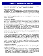
8. To prepare the overhead guy system, begin by
temporarily
installing a 2” U-bolt through the
TURNBUCKLE PLATE and into the top set of 2” U-bolt holes on the boom to mast plate. Add a couple
of 5/16” nuts to hold it in place. UNSCREW the turnbuckle eyes / hooks until only a thread or two
shows inside the turnbuckle body and hook them to turnbuckle plate.
9. Uncoil DACRON CORD. Secure one end to rear eyebolt, taking two turns through the eyebolt,
then adding three TIGHT half-hitches. Pull hard on cord to set the knots. Repeat for the front eyebolt.
Seal cord ends with heat (lighter, propane torch, etc) and tape to main length.
10. Equalize cord length at turnbuckle plate and cut. Put two turns trough rear turnbuckle eye. Pull the
Dacron rope as tight as possible and add three TIGHT half-hitches. Repeat for front cord section. Seal
and tape cord ends. When finished the overhead guys should be taught and laying parallel with the
boom. Now remove the turnbuckle plate from the boom to mast plate and lift it temporarily to note the
approximate height at which the boom becomes level. ( usually about 3 feet).
11. During final installation on the tower / mast, secure the turnbuckle plate at the appropriate height
with the 2” U-bolt. Then lean or pull on the cords to increase the tension and help the knots take their
final “set.” Make sure the knots are not slipping. When the guy system has taken a “set”, loosen the 2”
U-bolt and adjust turnbuckle plate height until boom is straight and level. Finer adjustments can be
made with the turnbuckles at any time, if necessary.
12. This completes the ASSEMBLY. REMEMBER to support the feedline at the antenna boom and on
the mast. Leave an adequate feedline loop for rotation around the tower. When stacking this antenna
with other H.F. models, maintain at least 8’ separation; more if practical. Mount horizontally polarized
VHF and UHF antennas at least 40” above or below this antenna to minimize interaction.
Carefully designed and manufactured by:
M
2
ANTENNA SYSTEMS, INC.
4402 N. SELLAND AVE.
FRESNO, CA 93722
(559) 432-8873 FAX: 432-3059
www.m2inc.com Email: sales@m2inc.com
10M4DX ASSEMBLY MANUAL
Summary of Contents for 10M4DX
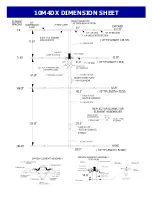
Page 4: ...10M4DX DIMENSION SHEET...
Page 5: ...D E PARASITIC ELEMENT DETAIL...


