393CP18 ASSEMBLY MANUAL
TYPICAL TOOLS REQUIRED: measuring tape, phillips screwdriver, 5/16”, 11/32, 7/16, and 1/2 spin-tite,
end wrenches and / or sockets. Heavy duty models may require larger sizes.
1. Lay out the boom sections and assemble using the DIMENSION
sheet as a guide for position and hardware.
2. Install the 8-32 x 1/4” set screw into each button insulator using
the 3/32” Allen wrench supplied.
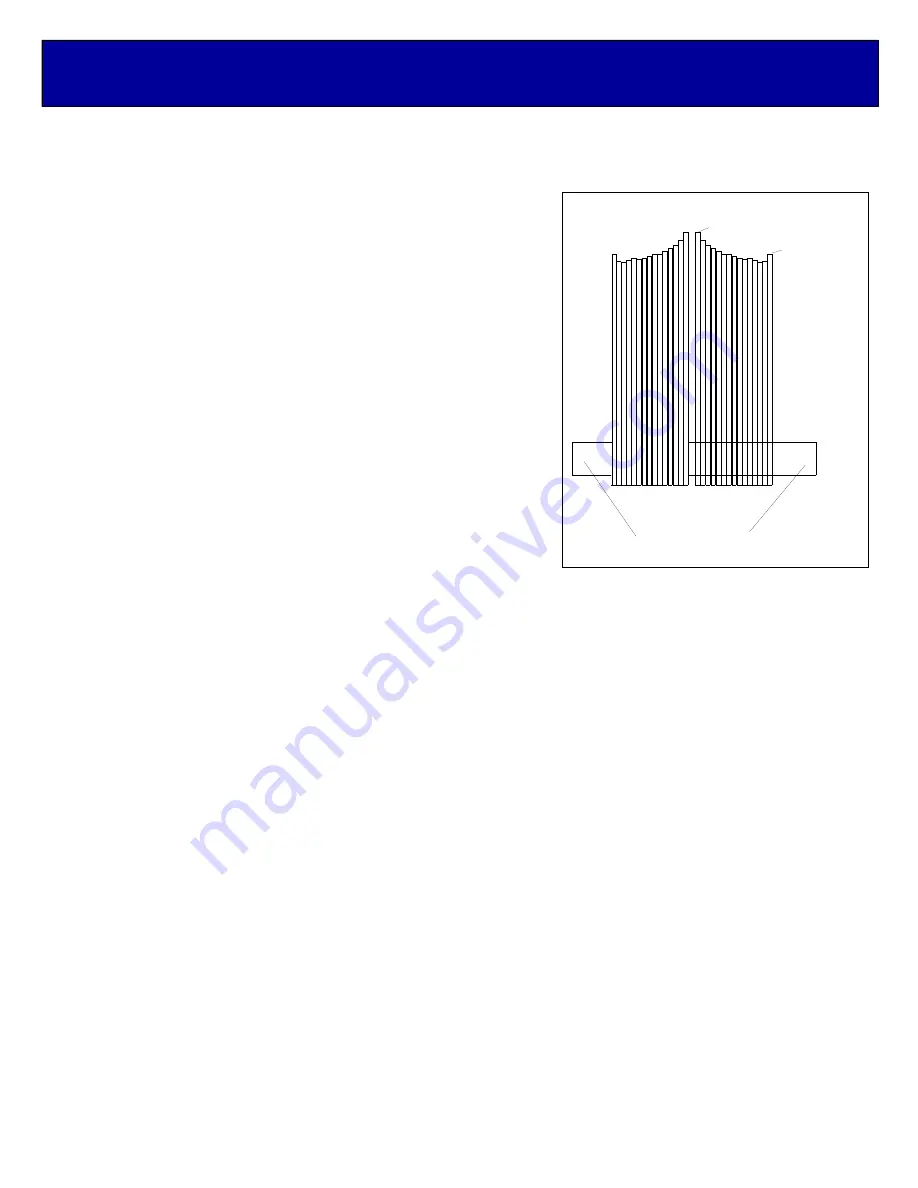
3. Cut a strip of masking tape about 6” long. Fold the ends under and
stick the tape to a flat surface, stickey side up.
Lay out the
elements by length and position as shown ON the
DIMENSION
SHEET
. Remove the REFLECTOR and find the rough center by
balancing it across finger. Push on a black button insulator to
about 1/2” from center. Insert the element through the holes at the
rear of the boom and install the second button. Install the 3/16”
rod DRIVEN ELEMENT as you did the reflector. Then continue
with the installation of the DIRECTORS.
Note that the Director
Elements may not consistently diminish in length from rear
to front, so pay close attention to length and position.
4. Now begin centering the elements. Use a tape measure to
EQUALIZE the amount the element sticking out on each side of
the boom. Once centered, tighten the set screw in the insulators
on each side. After all are centered, sight down the antenna from
the rear and compare tip symmetry. Look for any obvious
discrepancies and correct if found. REPEAT THESE STEPS AND
INSTALL THE OTHER PLANE OF ELEMENTS. NOTE THEY ARE SHIFTED FORWARD ON THE BOOM
BY 1/4 WAVELENGTH.
5. Mount the special REAR DRIVEN / POLARITY SWITCH FEED BLOCK to the boom using two (2)
8-32 X 1-1/4" screws. Orient with feed and balun connectors as shown on the Dimension Sheet. The ‘T’ block
unit mounts just behind the rear REFLECTOR element with one more 8-32 x 1-1/4” screw
7. Thread a 3/8” SEAL-NUT fully onto each ‘F’ connector on each block, with black Neoprene side facing out.
Generally the balun is installed in one loop. Attach balun to the block connectors and tighten
gently
using a
7/16" end wrench. The two medium length cables are the !/2 wave baluns. Then back the Seal Nuts out and
finger-tighten firmly up against the face of the connectors (or tighten
gently
with 1/2" end wrench). Later,
after the phasing lines are installed form the balun coax and phasing lines close to the boom and secure with
cable ties (snug but not crushing or kinking the coax).
8. Install the 8-32 x 1/4” set screws )using the 3/32” Allen) wrench into the SHORTING BARS. Slide the bars
onto the 3/16” rod driven element tips and the 1/8" Feed Block Rods. Position the Shorting Bars as specified
on the DIMENSION SHEET: the distance given is between the outer face of the Feed Block and the inner
face of the Shorting Bar. Align the bars and rods with each other and tighten the sets crews. NOTE: the
shorting bar dimensions may be different on the OPTIONAL circular switched driven element.
9. Now attach the phasing cables. The long, 3/4 wavelength coax cable goes to the the front driven element. And
the short cable goes to the rear driven element. Tighten the connectors lightly with a 7/16” end wrench and
then run the seal nut up against the face to the connector and tighten just one turn past finger tight with a 1/2”
end wrench.
10. Route the cables close to the boom and avoid crossing or touching the element butts to minimize detuning.
This is a critical area if the antenna match is to be preserved. Because the cables can couple into the field of
each element set, it is important to route the cables as shown and use the cable ties provided to keep the
cables tight against the boom. THIS COMPLETES THE ANTENNA ASSEMBLY.
MASKING TAPE
OR EQUIVALENT
FACE UP
ELEMENT PREPARATION
ELEPREP
M. STAAL
5-24-05
FRONT DIRECTOR
REFLECTOR


