M2 Antenna Systems, Inc. 4402 N. Selland Ave. Fresno, CA 93722
Tel: (559) 432-8873 Fax: (559) 432-3059 Web: www.m2inc.com
©2015 M2 Antenna Systems Incoporated
05/28/15
Rev.00
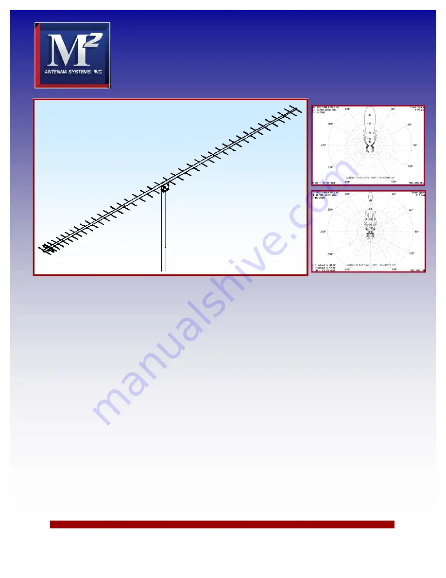
Model ......................................... 902-14WLC
Frequency Range ....................... 880 To 915 MHz
*
Gain .......................................... 21.14 dBi
Front to back .............................. 24 dB Typical
Beamwidth ............................... E=18° H=19°
Feed type ................................... Folded Dipole
Feed Impedance. ....................... 50 Ohms Unbalanced
Maximum VSWR ........................ 1.2:2 Typical at 902
Input Connector .......................... “N” Female
Power Handling .......................... 750 Watts
Boom Length / Dia ...................... 15’ 4” / 1”, 1-1/4” & 3/4”
Maximum Element Length .......... 6-3/8”
Turning Radius: .......................... 100”
Stacking Distance ....................... 43” High & 43” Wide
Mast Size .................................... 1-1/2” to 2” Nom.
Wind area / Survival ................... 1 Sq. Ft. / 100 MPH
Weight / Ship Wt. ........................ 6 Lbs. / 7 Lbs.
M2 Antenna Systems, Inc.
Model No: 902-14WLC
FEATURES:
The 902-14WL is the ultimate in performance and gain. The recently updated computer optimized design produc-
es excellent gain and VSWR across the band. It is ideal for stacking: a quad array will yield almost 25 dBd of real smoking
antenna gain. Tropo and EME should definitely be on your mind when owning one or more 902-14WLs! Structurally the
antenna is rugged, tapered-boom construction featuring 3/16 rod parasitics. A totally weather proof driven dipole design
means years of trouble free optimum performance. This antenna is a perfect compliment to your VHF-UHF antenna sys-
tem!
SPECIFICATIONS:
*Subtract 2.14 from dBi for dBd
Summary of Contents for 902-14WLC
Page 4: ...902 14WLC DIMENSION SHEET ...
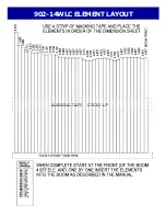
Page 5: ...902 14WLC ELEMENT LAYOUT ...


