CABLE ROUTING
Note:
When cable routing, each axis should be positioned at the centers of each travel spectrum. Az: If your AZ
is set for south center, then position the AZ at 180 deg. EL: if your EL is set for 0 to 90 deg. The set your EL for
45 deg. This way the cables will only need to flex for 1/2 of the total movement on each direction of rotation.
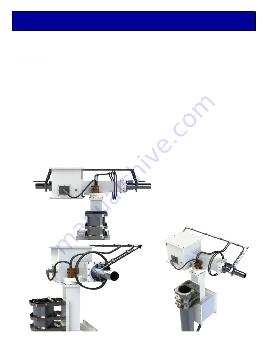
Elevation Loop
The Elevation axis control cable comes up through the AZ assembly cable pass through and attaches to the
elevation motor unit. Note the RF cables from the antennas come from either side of the H
-
Frame and onto the
cable bridge then they should loop around the Elevation axis body then down through the cable pass through.
The loop around the Elevation body will provide a loop that will expand and contract as the elevation moves up
or down in rotation. Temporarily use electrical tape or nylon ties to hold the cables together and to the cable
brace. Drive the Elevation axis to both ends of the travel and watch the cables to be sure they do not become to
tight or get hung up. Make adjustments as needed, this may take multiple passes to feel comfortable with the
cable rap and cable loop. Once you feel comfortable with the cable rap and its movement add nylon ties to the
cable brace. Note: multiple slots have been added to the cable brace to give adequate positions for small and
large cable bundles. Taping or the use of nylon tie to keep the bundle together below the cable pass through is
recommended
NOTE:
GENERIC POWER DIVIDER
BRIDGE SHOWN FOR
CABLE ROUTE EXAMPLE.
POWER DIVIDER BRIDGE
SETUP MAY BE DIFFERENT.
REFER TO MASTER SYSTEM
MANUAL FOR MORE DETAILS.
LARGE NYLON TIES
TO HOLD DOWN
POWER DIVIDERS
AND OR FEED LINES


