15
ver. 1.6.0.0
User Manual LadderLOGIX
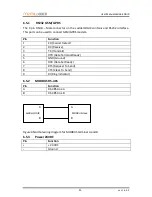
6.5.1
RS232 GSM/GPRS
The 9 pin DSUB – Male connector on the LadderLOGIX contains and RS232 interface.
This port can be used to connect GSM/GPRS modem.
Pin
Function
1
CD (Carrier Detect)
2
RX (Receive)
3
TX (Transmit)
4
DTR (Data Terminal Ready)
5
GND (Ground)
6
DSR (Data Set Ready)
7
RTS (Request To Send)
8
CTS (Clear To Send)
9
RI (Ring Indicator)
6.5.2
MODBUS RS-485
Pin
Function
A
RS-485 Line A
B
RS-485 Line B
6.5.3
Power 24VDC
Pin
Function
+
+ 24 VDC
-
Ground
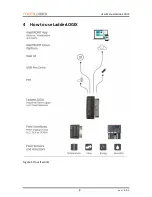
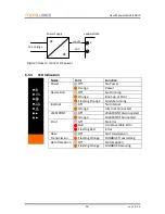
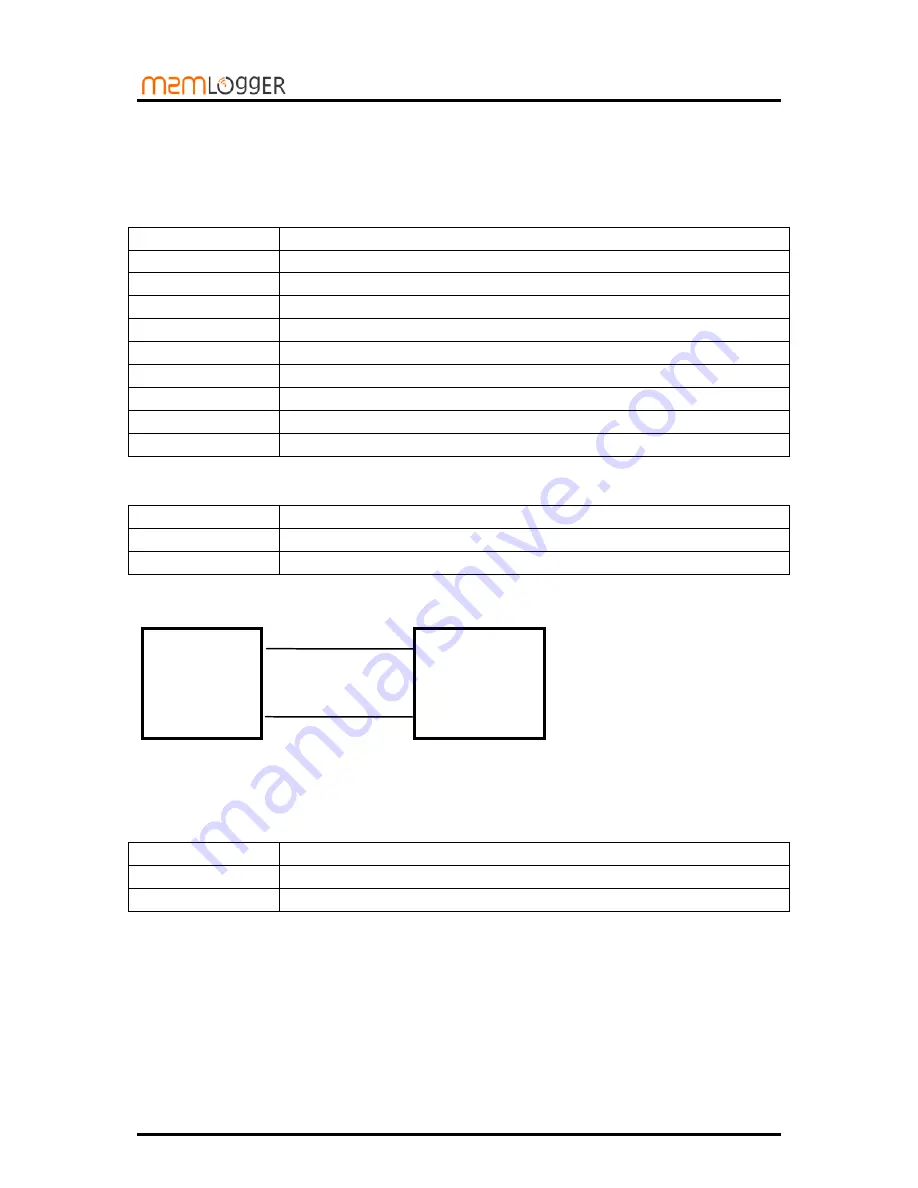
Figure 4 Normal wiring diagram for MODBUS terminal A and B
A
B
A
B
LadderLOGIX
MODBUS slave


