CROSBY
STEREO POWER AMPLIFIER
REVISION P
R
A – SEPTEMBER 2017
Copyright © 2017, M2Tech Srl
11
M2Tech
www.m2tech.biz
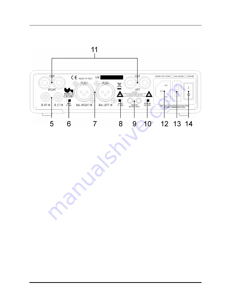
3. Back Panel
Figure 2
5) Single-ended inputs.
Connect a preamplifier provided with single-ended outputs.
Female RCA.
6) Input selector switch.
Allows to choose between single-ended and balanced inputs.
7) Balanced inputs.
Connect a preamplifier provided with balanced outputs. Female 3-pin
xlr connectors. 1 is GND, 2 is send, 3 is return.
8) Mode selector switch.
Allows to choose between stereo and bridged mono operation.
9) Trigger inputs.
A 12V trigger signal may be sent to one of this inputs to switch
CROSBY
on and off by the preamplifier or other trigger source. The two inputs are in parallel,
therefore the unused one may be used to forward the trigger signal to another unit (e.g. to
another
CROSBY
when two
CROSBY
are used in bridged mono mode to obtain more power
to drive difficult speakers).
10) Trigger enable switch.
When trigger is enabled, the
CROSBY
needs a trigger signal on
one of its trigger inputs to activate. When trigger is disabled, the
CROSBY
immediately
powers up when the read power switch is engaged.
11) Output binding posts.
Accept bare wire, forks, spades, lugs and bananas. Red is
positive and black is negative
12) Power cord socket.
Connect the stock power cord to this socket.
13) Fuse holder.
It holds 1 slow blow fuse, please read the information on rear panel for
the correct value for the selected mains voltage.


