background image

10

7.

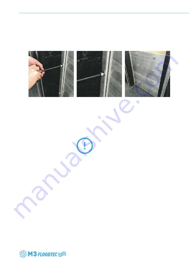
 Using the T-Bar tool 

supplied, apply two full turns 
to the vertical compression 
screws.

8.

 Starting from the bottom 

panel upwards, give the 
horizontal compression 
screws one full turn, the 
left and then the right, 
working up to the top.

WARNING: 
DO NOT OVER 
TIGHTEN

Any questions? Contact M3 Floodtec on +44 (0)1905 676467

* Panel 1 is determined by the fact it has two seals - top and bottom. 
* Panel 2 is determined by the fact it has only one middle seal on the top.
* Panel 2a is an additional Panel 2 for barriers with more than 3 panels.
* Panel 2 is determined by the fact  it has no seals.

9.

 Once this is completed 

your Stop Log barrier 
System will be ready 
to protect you and your 
property.

Summary of Contents for Stop Log Barrier

Page 1: ...Stop Log Barrier System Installation Guide ...

Page 2: ...an harness to enable us to deliver Innovative solutions that benefit the Environment and provide enhanced value to our Clients M3 Global Flood Technologies Ltd 9a Wassage Way Hampton Lovett Ind Est Droitwich Worcestershire WR9 0NX Tel 44 0 1905 676467 Email sales m3floodtec com 2 www m3floodtec com ...

Page 3: ...Stop Log Barrier System Contents Contents Introduction 4 Installation 6 Deployment 9 3 ...

Page 4: ...t and versatile designed to span wide distances and easily deployed in a flood situation The M3 Stop Log Barrier is suitable for use on residential and smaller commercial properties to protect doorway apertures against water ingress Introduction ...

Page 5: ...Stop Log Barrier System Introduction 5 ...

Page 6: ...bber wall post sealing pad in position so that wall post will compress and seal to the pad when fixed NOTE The vertical D seal is supplied so that its position is retained so that it is longer than the wall post This is to ensure that when the wall post is positions onto the EPDM pad the D seal will also seal into the pad 5 Use packing shims normally for double glazing easily available from builde...

Page 7: ...ion of the CT1 use some masking tape along the sides that will have CT1 applied to seal the edges This will allow excess CT1 to be kept away from sides and threaded holes and give a neat tidy finish to the finally applied areas 8 Hold the post in position with back against the wall so fixing screws can be inserted into top and bottom holes 9 Using spirit level and packing shims tighten all screws ...

Page 8: ...l the verticals and finish the aesthetic look of the installation 11 Trim off excess edges of EPDM pad under wall post and if required apply CT1 sealant adhesive in cases of rough ground without obstructing inner opening Installation Wall Rails Face Reveal 8 ...

Page 9: ... position also ensuring its bottom groove engages with the top of the middle panel 5 Once all panels have been pushed down so they fully engage with each other the compression blocks can be inserted and their bolts can then be finger tightened do not use tools at this stage 6 Push all panels towards the back of wall post onto the vertical D seal and then again by finger tightening only ensure all ...

Page 10: ...NING DO NOT OVER TIGHTEN Any questions Contact M3 Floodtec on 44 0 1905 676467 Panel 1 is determined by the fact it has two seals top and bottom Panel 2 is determined by the fact it has only one middle seal on the top Panel 2a is an additional Panel 2 for barriers with more than 3 panels Panel 2 is determined by the fact it has no seals 9 Once this is completed your Stop Log barrier System will be...

Page 11: ...Stop Log Barrier System Notes 11 Notes ...

Page 12: ...M3 Global Flood Technologies Ltd 9a Wassage Way Hampton Lovett Ind Est Droitwich Worcestershire WR9 0NX Tel 44 0 1905 676467 Email sales m3floodtec com m3floodtec com ...

Reviews:

Related manuals for Stop Log Barrier