background image

M3D Pro Disassembly- Alpha 
 

In this guide we will explain how to disassemble the Pro so you can remove the gantry’s and 
extruder. You will need a 2.0mm/1.5mm hex screwdriver for the disassembly and you’ll want to be 
in a antistatic environment. Some electronics will be exposed during the disassembly and there is 
a chance you could damage them. We recommend not working on a carpeted area and to 
discharge before working. You can do this by touching something metal (Not the printer) for at 
least one second. Wearing an antistatic wrist-wrap would be good. Link for a wrist-wrap here 

https://www.amazon.com/Rosewill-Anti-Static-Components-RTK-002-Yellow/dp/B004N8ZQKY/ref=
sr_1_1?ie=UTF8&qid=1494531998&sr=8-1-spons&keywords=anti+wrist+strap&psc=1


Although, it is highly recommended to use an antistatic wrist-wrap, if you do not have access to 
the antistatic wrist-wrap, you can do the repair process by having a metal contact to your body 
throughout the repair. 
 
Since the M3D PRO 3D printer is highly static device as there are various PCBs involved, if the 
repair process is carried out without following the above recommendation and the customer end 
up frying the electronics, they would need to send back their printers to M3D headquarters for 
replacement. The printer will still be covered under warranty but the replacement units will only be 
send by end of July.  
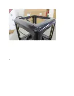
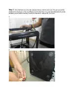
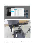


Step 1. 

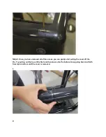
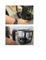
The first step will be to remove the front cover from the Pro. To do this you will need to 

remove the hex screws from the cover. There are a total of 8 screws in each cover. Four screws 
on the top and four screws on the bottom.  
 
1. 

Summary of Contents for PRO

Page 1: ...1 spons keywords anti static wrist strap psc 1 Although it is highly recommended to use an antistatic wrist wrap if you do not have access to the antistatic wrist wrap you can do the repair process b...

Page 2: ...2...

Page 3: ...removed all of the screws you can gently start pulling the cover off the Pro Try pulling out the top a little first and then move onto the bottom Keep going back and forth from top to bottom until the...

Page 4: ...3...

Page 5: ...n removed move onto the rear cover The process will be similar to the front cover The only difference will be that there is a grommet attached to the cable assembly on the bottom that may need to be r...

Page 6: ...3 4...

Page 7: ...5 Step 4 Once the front and back covers are removed you will be left with the box top rails These can easily be removed by just lifting them up and off the rods 1...

Page 8: ...emove the extruder and gantry s from the rods continue on with this step Next you will need to open the software and go to Setting Expert Controls Basic Controls Once there you will notice some arrows...

Page 9: ...2 Step 6 Once the extruder has reached the top and cannot go up any more than you should be able to remove the extruder without issue...

Page 10: ...1 2...

Page 11: ...able to pull the rods out of the sliders to remove the extruder from the X rods If you have one of our early Pro s then the rods might have been press fitted on To remove these you will need to twist...

Page 12: ...with this step Once the extruder is off you should be able to see the X gear and encoder wheel inside the holes where the X rods are inserted A encoder wheel rubbing up against the encoder could be c...

Page 13: ...r wheel and encode together then please continue with the next step Step 9 In this step we will disassemble the extruder core slightly to get a better photo of the encoder wheel and encoder Pinch the...

Page 14: ...X Board located on the right side of the extruder motor Step 11 Next we will unscrew the two hex screws holding the top of the extruder core in These are small so please keep them in a safe place so...

Page 15: ...1 2...

Page 16: ...can also insert the X rod with rack and move it back and forth to see if the encoder wheel is rubbing on the encoder Second Method In order to remove the print head housing Extruder Housing X housing...

Page 17: ...2 Gently pull the cable assembly out as shown in the picture below...

Page 18: ...ng out such you can get access to the screw that holds the X board as shown in the picture below 4 Once you remove the X board very carefully remove the E housing out making sure not to break the enco...

Page 19: ...ng carefully pull the X housing out In order to remove the X housing you would need to remove the two tabs that are present on the bottom section of the X housing out from their slots Refer to the fol...

Page 20: ...The above figure shows the two taps gold that needs to be pushed up in order to take the X housing out of the print head body...

Page 21: ...gainst the X rack assembly the X housing to the E housing by putting the two screws back together that joins the X housing to the E housing and install the X rack and rod by referring to the following...

Page 22: ...to resolve the issue of X gear grinding against the X rack check if the X encoder wheel is located in between the X encoder This is how the X gear with encoder and encoder wheel looks like from the bo...

Page 23: ...der wheel is located between the X encoder None of the black taps should come in contact with the encoder wheel as this can cause the encoder wheel to stall while the X motor is running which will in...

Page 24: ...axis grinding then please submit a ticket with tech support helpdesk printm3d com While submitting a ticket take a video with sound of moving the X axis back and forth so that we can better understand...

Page 25: ......

Page 26: ......

Reviews: