background image

10

10049018

2. 

Installing the base • Installation de la base • Instalación de la base

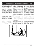
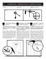
Remarque  :  Vérifiez  les  codes  de  

construction locaux avant l’installation 

d’un nouveau tuyau de drain.

Le tuyau de drain doit avoir 2” de diamètre 

(diamètre extérieur de 2 3/8”) et être centré 

à 12” des montants. Le haut du tuyau doit 

être lisse (sans ébarbures ou évase ment) 

et droit (sans angulation). Fig. 3.

Installez la base directement contre les 

montants et voyez à ce que le tuyau du 

drain soit centré par rapport à l’embout du 

drain. Fig. 4.
Pour l’assemblage et l’installation du 

drain, veuillez vous référer aux instructions 

fournies par le fabricant.

Dans l’éventualité où votre plancher ne 

serait pas de niveau, la base doit être 

supportée de manière à ce qu’elle procure 

un seuil de niveau pour aider au montage 

de la douche. Les supports doivent 

être répartis sous la base pour soutenir 

adéquatement.  Pour  le  vérifier,  marchez 

sur la base et cherchez les endroits où elle 

fléchit  sous  votre  poids,  particulièrement 

autour du drain.

Note: Check local building codes before 

installing new drain pipe.

The pipe should be 2” diameter (outside 

diameter should be 2-3/8”) and centered 

12” from the studs. The top of the pipe 

should be smooth (free of burr or flare) and 

straight (not on an angle). Fig. 3.

Install the base directly against the studs 

and confirm that the drain pipe is centered 

in the drain head. Fig. 4.

For the assembly and installation of the 

drain, please refer to the manufacturer’s 

instructions.

To compensate for any irregularities in your 

floor, the base must be shimmed properly 

from underneath to provide a level threshold 

for mounting purposes. Any shims must 

support the entire base: not only at one 

point. Verify this by standing on the base, 

once shimmed, and check for any spring or 

bounce in the base. Particularly near drain 

area.

Advertencia: Compruebe las normas 

locales de obra antes de instalar una 

nueva tubería de desagüe.

El tubo de desagüe debe tener 2 pulgadas 

de diámetro interior (diámetro exterior 

de 2 3/8”) y estar centrado a 12” de los 

montantes o jambas murales. La parte 

superior del tubo debe ser lisa (sin rebabas 

ni ensanches) y recta (no angulosa). Fig. 3.
Instale la base directamente contra las 

jambas y asegúrese de que el tubo de 

desagüe está centrado respecto del 

colector de desagüe. Fig. 4.
Para el ensamblaje e instalación del 

desagüe,  refiérase  a  las  instrucciones  del 

fabricante.

Suplementar la base con cuñas de ajuste, 

desde abajo, para compensar por cualquier 

irregularidad en su piso y proveer un 

umbral a nivel, para el montaje. Los cuñas 

de ajuste deben sustentar toda la base y 

no sólo un punto. Verificar parándose sobre 

la base, una vez nivelada; observar si hay 

salto o rebote en la base, especialmente en 

el área del drenaje.

5"

(127 mm)

2 1/4"

(57 mm)

Drain pipe

Drain

Tubo de desagüe

Wall Stud (Framing)

Montant mural (Structure)

Montantes murales (estructura)

Sub floor

Faux plancher

Contrapiso

Finished wall

Revêtement de finition

Revestimiento de acabado

12"

(305 mm)

Shower base

Base de douche

Base de ducha

Fig. 3

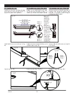
#8 x 1 1/4"

Flat Head Screw (recommended)

Vis à tête plate (recommandé)

Tornillo de cabeza plana (recomandada)

Ø3/16"

Note: 

Use shims behind the fastening flange as required.

Note : 

Utiliser des cales derrière la lèvre de lixation au besoin.

Nota : 

Utilizar cuñas de madera detrás de la brida de fijación si es necesario.

Important: Hand tighten only!

Important: Serrer à la main seulement

Importante: Apretar solamente con la mano

With a 3/16" bit, drill holes in the base flange 

then secure the base to the wall studs with 

#8 x 1¼ " screws.

Percer des trous dans le rebord de fixation 

de la base à l'aide d'une mèche de 3/16".  

Visser la base aux poteaux de cloison à 

l'aide de vis #8 x 1¼".

Con una broca de 3/16" de diámetro, haga  

perforaciones en el reborde de fijación de la 

base. Atornille la base a las soportes con los 

tornillos de #8 x 1¼"

Fig. 4

Summary of Contents for 105539

Page 1: ...RVER POUR UN USAGE ULT RIEUR CONSERVEESTEMANUALCOMOREFERENCIA Read all instructions carefully before proceeding Lire toutes les instructions attentivement avant de commencer l installation Leer deteni...

Page 2: ...2 10049018...

Page 3: ...er installation of your shower Introduction 3 Before you begin 4 General considerations 5 Warning 5 Parts and components 6 Tools and supplies required 8 1 Preparing the shower area 9 2 Installing the...

Page 4: ...including all screws and hardware see itemized Parts List on Page 6 Move the unit close to where it is to be installed before beginning the work If necessary disassemble sections of the unit before mo...

Page 5: ...taraudeuses Une bonne lubrification est n cessaire afin de faciliter le montage Serrez les vis la main N utilisez pas de perceuse lectrique cette fin Note La base doit tre install e directement contre...

Page 6: ...vot r glable Cojinete de pivote ajustable 1 n a 15 M5 X 1 4 setscrew Vis de serrage M5 X 1 4 Tornillo de fijaci n M5 de 1 4 1 n a 16 Glass bushing Douille pour verre Cojinete para vidrio 2 n a 17 15mm...

Page 7: ...1 2 1 2 1 2 1 4 11 2 11 1 2 1 2 3 8 3 8 Parts and components Liste des pi ces et composantes Piezas y Componentes 8 1 2 1 2 1 4 11 2 11 1 2 1 2 3 8 3 8 1 2 1 2 1 4 11 2 11 1 2 1 2 3 8 3 8 7 9 10 21 2...

Page 8: ...cquer thinner or acetone Utility knife Caulking Gun Safety glasses Serrated Spreader Cutting pliers Supplies required 2 cartridges of wall adhesive polystyrene compatible 1 cartridge of siliconized la...

Page 9: ...ud wall corner Fig 1 Note the base is installed against the studs not the finished walls If necessary remove finished wall to expose studs Fig 2 Confirm that the walls are vertical plumb within 3 8 sq...

Page 10: ...tencia Compruebe las normas locales de obra antes de instalar una nueva tuber a de desag e El tubo de desag e debe tener 2 pulgadas de di metro interior di metro exterior de 2 3 8 y estar centrado a 1...

Page 11: ...er It is strongly recommended that raw plaster or new wallboard be primed or water sealed prior to installation If the panels are being installed over existing tile and over 30 of the tiles are remove...

Page 12: ...l and check to see if the holes have been drilled in the right locations Midiendo a partir de la base de la ducha y de las l neas verticales de la pared determine con exactitud el emplazamiento de la...

Page 13: ...ficios de las llaves No se acerque a m s de una pulgada de las partes formadas y las paredes de los paneles Aplique el adhesivo detr s de los paneles como se muestra en la fig 7a y con una llana denta...

Page 14: ...p of adhesive behind the corner caddy as illustrated in Fig 9 Place the corner caddy in the shower corner and align the top of the corner caddy with the top of the wall panels Follow the ADHESIVE INST...

Page 15: ...panel by separating it from the wall jamb Mark the location of the mounting holes of the wall jamb Fig 11 If the wall jamb is leaning against a wood stud drill holes where marked with a 1 8 drill bit...

Page 16: ...ado opuesto al rociador de la ducha Adem s no debe haber ning n obst culo que impida la abertura completa de la puerta Fig 14 Side panel assembly C t pivot Montaje Panel Lateral Right side hinging Piv...

Page 17: ...el lado que haya elegido para abrir la puerta como se muestra arriba en la Fig 15 Right side hinging Pivot droite Bisagra a la derecha Left side hinging Pivot gauche Bisagra a la izquierda Fixer la t...

Page 18: ...7a 17b Screw on the hinges using the 5 32 Allen key and the 1 4 20 x 1 2 screws Do not over tighten Con cuidado apoye la puerta en el piso del lado opuesto a los agujeros que permiten sujetar las bisa...

Page 19: ...Fig 20 Fasten everything to the top rail with the cap washer the Phillips no 10 24 x screw and a snap cap Fig 20 ATENCI N Entre esta etapa y la etapa 14 trabaje con mucha precauci n La ducha no est t...

Page 20: ...a Phillips 2 screwdriver adjust the adjustment screws located on the pivots To do so one person should hold the door in the open position while the other is making the adjustments Fig 21a Cierre la pu...

Page 21: ...door hinge and the pivot block to engage the hexagonal top of the adjustable pivot bushing Fig 22a and Fig 22b Once the adjustement is done tighten the setscrew Note For proper operation there should...

Page 22: ...ll bit drill the extrusion built into the wall jamb where there are oblong holes Fasten the extrusions to the wall jambs with the Phillips square 2 6 X 1 2 screws IMPORTANT Do not use an electric dril...

Page 23: ...t apposer un joint aimant sur la porte Fig 26a et un joint aimant sur le panneau lat ral situ sur le c t de l ouverture de la porte Fig 25a 15 2 Installing the door magnets For a leak proof shower ins...

Page 24: ...r t e D o o r D o o r P u e r t a NOTE The glass clamps have recessed areas that allow room for the U shaped part of the hinge side door seal The seal strip should cover the entire length of the glass...

Page 25: ...n alrededor de los accesorios de plomer a Selle las juntas de manera uniforme Vuelva a colocar o instale los grifos y el cabezal de ducha Espere 24 horas antes de utilizar la ducha Fig 30 hours heure...

Page 26: ...prevenir la aparici n de diferentes tipos de bacterias que suelen desarrollarse en los dep sitos que se acumulan en las duchas y ba eras a trav s del tiempo Los paneles transl cidos la base o plato d...

Page 27: ...y extends only to the original owner end user for personal household use For commercial uses additional limitations apply For accessing product Limited warranty please visit www maax com ca warranty L...

Page 28: ...2020 MAAX Bath Inc PRINTED IN CANADA IMPRIM AU CANADA IMPRESO EN CANADA 2020 09 18 10049018 www maax com Technical Services Service technique Servicio t cnico T 1 877 438 6229 F 1 888 361 2045...

Reviews: