background image

15

10049018

7. 

Installing the wall jambs • Installation des montants muraux  

• Instalación de los montantes murales 

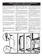
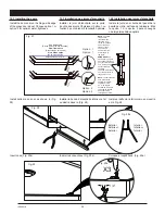
Insérer le panneau latéral (partie extrusion 

métallique) dans le montant mural en 

prenant soin d'aligner les trous oblongs du 

montant mural vers l'intérieur de la douche 

(Fig. 10a).
Insérer ensuite le panneau latéral dans les 

deux encoches de la base et bien pousser 

ce panneau contre le mur, de sorte à ce 

que le montant mural soit en contact direct 

avec le mur (Fig. 10b). Mettre de niveau et 

marquer l’emplacement du montant mural 

Fig. 10. 
Retirer le panneau latéral en le retirant 

du montant mural. Marquer les trous de 

fixation du montant mural (Fig. 11).

Si le montant mural s'appuie contre un 

montant de bois, percer aux endroits 

marqués à l'aide d'une une mèche de 1/8 

po (Fig. 12). Fixer le montant mural à l'aide 

des vis fournies #8 x 1 1/2 po (Fig. 12a).
Si le montant mural ne s'appuie pas contre 

un montant de bois percer aux endroits 

marqués à l'aide d'une une mèche de 1/4. 

Insérer les ancrages remettre le montant en 

place et le fixer à l'aide des vis fournies ( #8 

x 1 1/2 po ) Fig. 12b.

REMARQUE: Pour faciliter l'installation, 

commencer par la partie inférieure. 

S'assurer que le tout est de niveau.
Répéter les étapes pour le second 

montant mural.

Insert the side panel with the metal 

extrusion  trim into the wall jamb by aligning  

the oblong holes of the wall jamb carefully 

so that they are facing the inside of the 

shower (Fig. 10a).
Then lower the side panel into the two 

slots on the base and push it firmly enough 

against the wall  so as the wall jamb is in 

direct contact with the wall (Fig. 10b). Level 

the wall jamb and mark its location (Fig. 10).

Remove the side panel by separating it 

from the wall jamb. Mark the location of the 

mounting holes of the wall jamb (Fig. 11).
If the wall jamb is leaning against a wood 

stud,  drill holes where marked with a  1/8” 

drill bit (Fig. 12). Fasten the wall jamb with 

the #8 x 1 1/2“ screws provided (Fig. 12a).

If the wall jamb is not leaning against a 

wood stud, drill holes where  marked with 

a 1/4” drill bit. Insert anchors. Replace the 

wall jamb and fasten it with the  #8 x 1 1/2“ 

screws provided (Fig.12b).


NOTE: For easier installation, start at the 

bottom of the wall jamb. Make sure that 

it is level.
Repeat these steps for the second wall 

jamb.

Inserte el panel lateral (la parte que tiene el 

perfil metálico) dentro del montante mural 

y alinee cuidadosamente los agujeros 

rectangulares del montante mural hacia el 

interior de la ducha (Fig. 10a).
A continuación, inserte el panel lateral en 

las dos ranuras de la base y presiónelo con 

fuerza contra la pared para que el montante 

mural entre en contacto directo con la 

pared (Fig. 10b). Nivele el montante mural 

y marque su ubicación (Fig. 10).
Separe el panel lateral del montante mural 

para retirarlo. Marque la ubicación de los 

agujeros de montaje del montante mural 

(Fig. 11).
Si el montante mural está apoyado contra 

un montante de madera, haga agujeros en 

los lugares marcados con una broca de 1/8” 

(Fig. 12). Sujete el montante mural con los 

tornillos Nro. 8 de 1½" provistos (Fig. 12a).
Si el montante mural no está apoyado 

contra un montante de madera, haga 

agujeros en los lugares marcados con 

una broca de 1/4". Inserte los anclajes. 

Coloque nuevamente el montante en su 

sitio y sujételo con los tornillos Nro. 8 de 

1½” provistos (Fig. 12b).

NOTA: Para facilitar la instalación, 

comience por la parte de abajo del 

montante mural. Asegúrese de que esté 

a nivel. 

Repita estas etapas para el segundo 

montante mural.

Fig. 10b

Fig. 10a

Fig. 10

Fig. 11

Fig. 12

Fig. 12a

Fig. 12b

X4

X4

Summary of Contents for 105539

Page 1: ...RVER POUR UN USAGE ULT RIEUR CONSERVEESTEMANUALCOMOREFERENCIA Read all instructions carefully before proceeding Lire toutes les instructions attentivement avant de commencer l installation Leer deteni...

Page 2: ...2 10049018...

Page 3: ...er installation of your shower Introduction 3 Before you begin 4 General considerations 5 Warning 5 Parts and components 6 Tools and supplies required 8 1 Preparing the shower area 9 2 Installing the...

Page 4: ...including all screws and hardware see itemized Parts List on Page 6 Move the unit close to where it is to be installed before beginning the work If necessary disassemble sections of the unit before mo...

Page 5: ...taraudeuses Une bonne lubrification est n cessaire afin de faciliter le montage Serrez les vis la main N utilisez pas de perceuse lectrique cette fin Note La base doit tre install e directement contre...

Page 6: ...vot r glable Cojinete de pivote ajustable 1 n a 15 M5 X 1 4 setscrew Vis de serrage M5 X 1 4 Tornillo de fijaci n M5 de 1 4 1 n a 16 Glass bushing Douille pour verre Cojinete para vidrio 2 n a 17 15mm...

Page 7: ...1 2 1 2 1 2 1 4 11 2 11 1 2 1 2 3 8 3 8 Parts and components Liste des pi ces et composantes Piezas y Componentes 8 1 2 1 2 1 4 11 2 11 1 2 1 2 3 8 3 8 1 2 1 2 1 4 11 2 11 1 2 1 2 3 8 3 8 7 9 10 21 2...

Page 8: ...cquer thinner or acetone Utility knife Caulking Gun Safety glasses Serrated Spreader Cutting pliers Supplies required 2 cartridges of wall adhesive polystyrene compatible 1 cartridge of siliconized la...

Page 9: ...ud wall corner Fig 1 Note the base is installed against the studs not the finished walls If necessary remove finished wall to expose studs Fig 2 Confirm that the walls are vertical plumb within 3 8 sq...

Page 10: ...tencia Compruebe las normas locales de obra antes de instalar una nueva tuber a de desag e El tubo de desag e debe tener 2 pulgadas de di metro interior di metro exterior de 2 3 8 y estar centrado a 1...

Page 11: ...er It is strongly recommended that raw plaster or new wallboard be primed or water sealed prior to installation If the panels are being installed over existing tile and over 30 of the tiles are remove...

Page 12: ...l and check to see if the holes have been drilled in the right locations Midiendo a partir de la base de la ducha y de las l neas verticales de la pared determine con exactitud el emplazamiento de la...

Page 13: ...ficios de las llaves No se acerque a m s de una pulgada de las partes formadas y las paredes de los paneles Aplique el adhesivo detr s de los paneles como se muestra en la fig 7a y con una llana denta...

Page 14: ...p of adhesive behind the corner caddy as illustrated in Fig 9 Place the corner caddy in the shower corner and align the top of the corner caddy with the top of the wall panels Follow the ADHESIVE INST...

Page 15: ...panel by separating it from the wall jamb Mark the location of the mounting holes of the wall jamb Fig 11 If the wall jamb is leaning against a wood stud drill holes where marked with a 1 8 drill bit...

Page 16: ...ado opuesto al rociador de la ducha Adem s no debe haber ning n obst culo que impida la abertura completa de la puerta Fig 14 Side panel assembly C t pivot Montaje Panel Lateral Right side hinging Piv...

Page 17: ...el lado que haya elegido para abrir la puerta como se muestra arriba en la Fig 15 Right side hinging Pivot droite Bisagra a la derecha Left side hinging Pivot gauche Bisagra a la izquierda Fixer la t...

Page 18: ...7a 17b Screw on the hinges using the 5 32 Allen key and the 1 4 20 x 1 2 screws Do not over tighten Con cuidado apoye la puerta en el piso del lado opuesto a los agujeros que permiten sujetar las bisa...

Page 19: ...Fig 20 Fasten everything to the top rail with the cap washer the Phillips no 10 24 x screw and a snap cap Fig 20 ATENCI N Entre esta etapa y la etapa 14 trabaje con mucha precauci n La ducha no est t...

Page 20: ...a Phillips 2 screwdriver adjust the adjustment screws located on the pivots To do so one person should hold the door in the open position while the other is making the adjustments Fig 21a Cierre la pu...

Page 21: ...door hinge and the pivot block to engage the hexagonal top of the adjustable pivot bushing Fig 22a and Fig 22b Once the adjustement is done tighten the setscrew Note For proper operation there should...

Page 22: ...ll bit drill the extrusion built into the wall jamb where there are oblong holes Fasten the extrusions to the wall jambs with the Phillips square 2 6 X 1 2 screws IMPORTANT Do not use an electric dril...

Page 23: ...t apposer un joint aimant sur la porte Fig 26a et un joint aimant sur le panneau lat ral situ sur le c t de l ouverture de la porte Fig 25a 15 2 Installing the door magnets For a leak proof shower ins...

Page 24: ...r t e D o o r D o o r P u e r t a NOTE The glass clamps have recessed areas that allow room for the U shaped part of the hinge side door seal The seal strip should cover the entire length of the glass...

Page 25: ...n alrededor de los accesorios de plomer a Selle las juntas de manera uniforme Vuelva a colocar o instale los grifos y el cabezal de ducha Espere 24 horas antes de utilizar la ducha Fig 30 hours heure...

Page 26: ...prevenir la aparici n de diferentes tipos de bacterias que suelen desarrollarse en los dep sitos que se acumulan en las duchas y ba eras a trav s del tiempo Los paneles transl cidos la base o plato d...

Page 27: ...y extends only to the original owner end user for personal household use For commercial uses additional limitations apply For accessing product Limited warranty please visit www maax com ca warranty L...

Page 28: ...2020 MAAX Bath Inc PRINTED IN CANADA IMPRIM AU CANADA IMPRESO EN CANADA 2020 09 18 10049018 www maax com Technical Services Service technique Servicio t cnico T 1 877 438 6229 F 1 888 361 2045...

Reviews: