background image

# 10049321-

090804

8

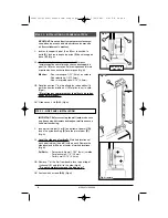
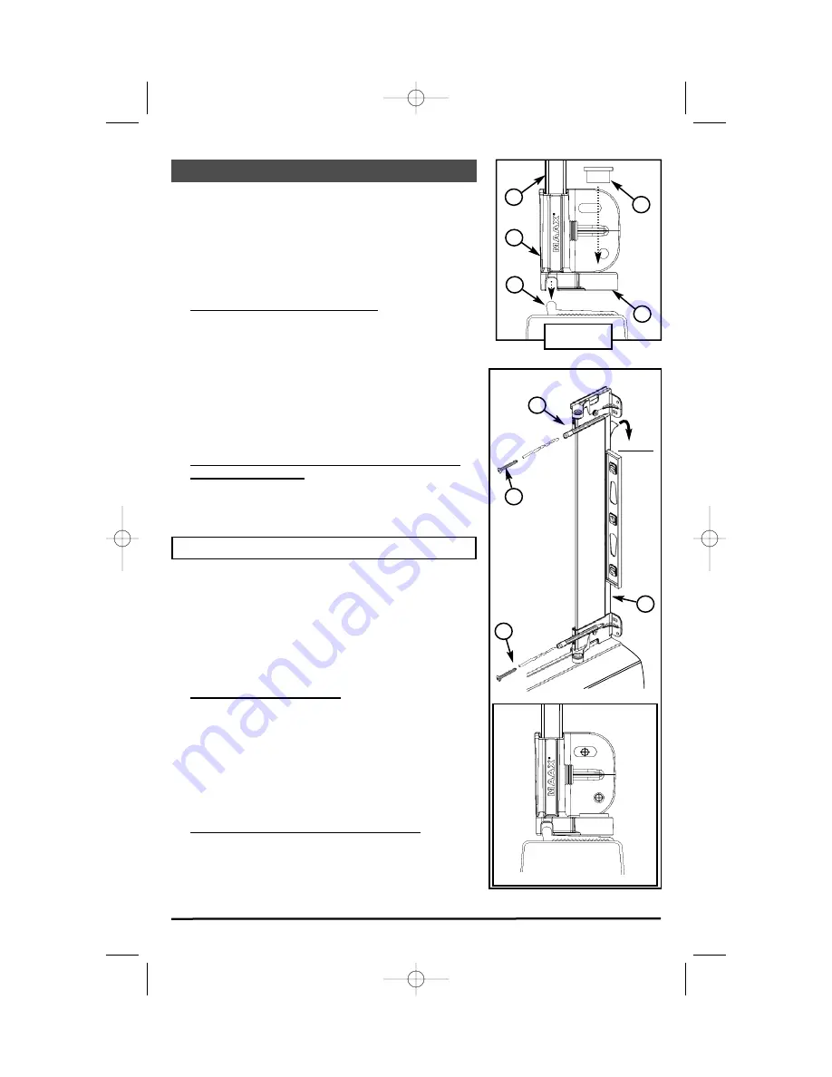
STEP 5  - SIDE PANEL INSTALLATION

IMPORTANT: Before securing the wall jamb, make sure
you have a wood structure behind your wall to ensure a
solid wall anchoring.

I.

Insert pivot retainer 

(J

or 

K)

on bottom of door sill 

(G)

.

Insert the nylon bushing 

(S)

into the pin retainer 

(R)

.

(Fig. G)

II.

Level the side panel vertically.

Mark hole locations of

each pivot retainer (

J

and 

K

) with a pencil. Remove the

side panel and drill holes at center of marked locations .

(Fig. H)

Drill bits:

- For ceramic tile wall: 7/32” (6mm) carbide
- For plastic wall: 1/8” (3,2mm)
- For dry wall: 3/16’’ (4,8mm)

III.

Remove 1” of the film from double-face tape at top of
U-channel 

(F) 

and fold it to the side

(Fig. H)

**Do not completely remove the tape now.** 

IV

.

Fasten with 4 screws 

(AA)

.

(Fig. H)

ÉTAPE 5 - INSTALLATION DU PANNEAU LATÉRAL

MPORTANT: Avant de fixer le montant mural assurez-
vous d’avoir un cadre de bois derrière votre mur afin
de fixer solidement le montant. 

I.

Insérez le support à pivot 

(J

ou

K)

sur le seuil de la

porte 

(G)

. Insérez la bague de nylon 

(S)

dans le support

d’axe 

(R)

.

(Fig. G)

II.

Nivelez verticalement le panneau latéral.

Marquez

l’emplacement des ouvertures de chacun des supports à
pivot (

J

et 

K

) avec un crayon. Enlevez le panneau latérale

et percez les trous au centre des marques.

(Fig. H)

Mèches:

-Pour céramique: 7/32” (6mm) au carbure
-Pour plastique: 1/8”(3,2mm)
-Pour mur préfabriqué: 3/16’’ (4,8mm)

III.  

Décollez environ 1” de la pellicule du ruban adhésif à
partir du haut du profilé en U

(F) 

et pliez le sur le côté.

(Fig. H)

**Ne retirez pas completement  la pellicule du ruban
adhésif maintenant.** 

IV.

Vissez avec 4 vis

(AA). 

(Fig. H)

S

G

Vue de côté /

Side View

J/K

Fig. G

R

Fig. H

J/K

B

Pellicule

Film

AA

AA

F

Fig. H (detail)

10049321-060301(kleara 6mm single pivot).qxp  7/20/2006  2:49 PM  Page 8

Summary of Contents for KLEARA 6MM PIVOT

Page 1: ...vant de commencer Please read instructions before proceeding KLEARA 6MM PIVOT KLEARA 6MM PIVOT Porte de douche simple Single shower door F H I N G M J K J K O E L D CC AA AA S R Q T P B A BB H I C Opt...

Page 2: ...J 10048068 XXX 601 K 10048068 XXX 602 G 10041369 M 10048170 092 AA 10047011 BB 10047235 CC 10048136 ILLUSTRATION DES PI CES ILLUSTRATION OF COMPONENTS SAC DE QUINCAILLERIE HARDWARE BAG F 10041152 Q 1...

Page 3: ...7011 10047235 10048136 PIECE PIECE PANNEAU PORTE ASSEMBL 6MM PIVOT PANNEAU DE VERRE LAT RAL MONTANT PERCUTEUR MONTANT MURAL MONTANT AJUSTABLE PROFIL EN U SEUIL CHARNI RE DE VERRE SUP RIEURE CHARNI RE...

Page 4: ...tub door is in good condition and make sure that all parts are included in the hardware bag If you have a problem please contact your distributor immediately Required equipment Phillips 1 and 2 screw...

Page 5: ...icone dans les rainures sous le seuil Fig C IV Installez et retenez en place l aide de ruban masquer Fig D STEP 2 SILL INSTALLATION I Measure door opening along the mark made in step 1 II Cut sill G t...

Page 6: ...install l tape pr c dente IV Ins rez le deuxi me support pivot J ou K l autre extr mit du panneau de verre lat ral B jusqu au profil en U I Insert a pivot retainer J or K on the end of the side panel...

Page 7: ...screw P STEP 4 SIDE PANEL ASSEMBLY NEXT I Serrez les vis de pression P contre le panneau de verre lat ral B en utilisant la cl Allen fournie avec le support pivot J ou K Fig F Note Ne pas trop serrez...

Page 8: ...ON DU PANNEAU LAT RAL MPORTANT Avant de fixer le montant mural assurez vous d avoir un cadre de bois derri re votre mur afin de fixer solidement le montant I Ins rez le support pivot J ou K sur le seu...

Page 9: ...profil en U L entre le pan neau de verre lat rale B et le profil en U F Coupez l exc dent Fig R STEP 6 DOOR ASSEMBLY I Remove film from double face tape at top of U channel F Slowly pull down on film...

Page 10: ...de la porte Fig I II Installez la poign e de porte N Fig J STEP 7 DOOR ASSEMBLY I Insert gasket O onto the door panel A Install gasket O between glass clamps H I Cut excess at top of door Fig I II Ass...

Page 11: ...K Fig L STEP 8 DOOR PANEL INSTALLATION I Remove pin retainer R by unscrewing set screw Q Use allen key provided with pivot retainer Fig K II Insert the BOTTOM PIN of the glass clamp H or I into the ny...

Page 12: ...3 16 4 8mm IV Vissez le montant mural avec les vis AA Fig N STEP 9 WALL JAMB INSTALLATION IMPORTANT Before securing the wall jamb make sure you have a wood structure behind your wall If it is not the...

Page 13: ...aide de trois vis BB Fig P STEP 10 DOOR ADJUSTMENT I Level the door A using the adjustment screws on the top and bottom glass clamps H or I Fig O II Insert the expanding jamb E inside the wall jamb D...

Page 14: ...DES JOINTS D TANCH IT I Ins rez le d flecteur M sur le bas de la porte A Coupez l exc dent Fig T II Ins rez la garde d claboussure CC sur la charni re inf rieure H ou I Fig S STEP 11 GASKETS INSTALLAT...

Page 15: ...sh NETTOYAGE TO CLEAN Les nettoyeurs m nagers liquides doux sont suffisants pour garder la surface propre et brillante Rincez fond et ass chez avec un chiffon propre ATTENTION Les d tergents en poudre...

Page 16: ...c de pas l installation n engage pas d entrepreneur cet effet ni ne supervise l installation et cons quemment ne peut tre tenue responsable de tout d faut bris ou dommage caus directement ou indirecte...

Page 17: ...e couvert par la garantie 2 l utilisateur a inform un agent autoris de MAAX ou un repr sentant du service de la garantie de la nature du probl me durant la p riode de la garantie 3 une preuve concluan...

Page 18: ...a contractor for this purpose and consequently cannot be held responsible for any defect breakage or damage caused thereby or resulting thereof either directly or indirectly The owner end user must p...

Page 19: ...1 the failure is of the nature or type covered by the warranty 2 the user has informed an authorized MAAX Agent or Warranty Service Department representative of the nature of the problem during the w...

Page 20: ..._____________________ No ____________________________________________________ Save this manual for future reference Conservez ce manuel pour usage ult rieur KEEP THESE INFORMATIONS CONSERVEZ CES INFOR...

Reviews: