


EN
16
When connecting the supply cable to the mains, re-
member that:
the yellow-green (protective) conductor must be
–
connected to the protective (earth) terminal mar-
ked with
,
the blue conductor is a neutral conductor,
–
the brown, black and red conductors are phase
–
(live) conductors,
the conductors must not be in contact with hot
–
surfaces whose temperature exceeds 75
0
C,
if your cooker does not have a mains supply ca-
–
ble, an H05RR-F or H05V2V2-type cable with an
appropriate cross section should be used
Possible wiring diagrams are shown in Figures 7.1.1
and 7.1.2.
If the cooker has a terminal strip, connect the sup-
•
ply cable (
1
) to the strip terminals (
2
) according to
the diagram affixed to the inside of the cover (
3
)
(7.1.3). For this purpose, remove the screws (
5
)
which fix the cover (
3
) to the backside of the co-
oker.
The terminal strip located on the backside (
•
7
) of
the cooker has six screw terminals, including three
phase (live) terminals marked with the symbols L1-
L2-L3 and two neutral terminals N-N (7.1.1). The
terminals should be shorted. Three jumpers are at-
tached to the terminal strip. The protective terminal
is marked with the symbol
.
Fix the supply cable (
•
1
) in the connection clamp (
4
)
with the use of 4 screws. Access to those screws
is through the slots situated below the holes (
6
)
(7.1.3).
When the cooker is connected, rotate the cover (
•
3
)
by 180
0
about the vertical axis, and then fit it to the
cooker backside with the catches (
8
) placed in the
holes (
6
), press it to the cooker backside and tigh-
ten with the screws (
5
).
Wipe the enamelled and glass surfaces with a soft
•
damp cloth.
Before using the appliance for the very first time,
•
we recommend heating particular cooking zones
for about 3 minutes, without putting dishes on
them.
Remove the equipment and foil from the oven and
•
clean it with warm water with added detergent.
Before the first use, close the oven door and turn
•
the oven on for ca. 30 minutes. The oven must be
empty when heated. Turn the oven control knob
to
, and the temperature adjustment knob to
250°C. The smoke and smell produced during this
procedure are only slight, provided that the room is
well ventilated, e.g. by opening the windows. After
it has cooled down, clean the oven according to
instructions set forth in section “Cleaning and Ma-
intenance”.
9.1 Stage control
The knob can be rotated in both directions within the
range of 0 - 360
0
. The lowest heating power is ob-
tained by turning the knob to position “1” with the hi-
ghest heating power at the position marked „6”.
In order to quickly warm up or boil a dish, set the
knob to position „6”, and then reduce the power if
necessary by turning the knob clockeise.
The cooking zones and their corresponding knobs
are shown in fig. 9.1.2.
9.2 Cooking zone indicator
Heating of the cooking zones is signalled by the
•
special indicator which is located in the front part
of the hob (9.2.1).
When the cooking zones are hot, then the light in-
•
dicators corresponding to particular zones will light
up.
The light indicators lights up when the cooking
•
zone temperature reaches approximately 50
0
C.
The indicator light may burn down and then there
•
is no indication that the corresponding zone is hot.
In such a case, call the nearest authorised service
shop.
9.3 Selecting pots for the hot plates
Choice of cookware is a basic condition of proper
•
use of the ceramic plate.
Cookware should always be clean and dry as they
•
will the conduct and retain heat well.
Pot bottoms should be flat, even and thick, and
•
their diameter should be equal or somewhat larger
than that of the heating fields. If the pot’s diameter
is smaller than that of a heating field, large amount
of heat will be unused.
Uneven pot bottom results in longer cooking time
•
and increased current consumption.
During cooking, pan lids should be used. The pan
•
lids should not be bigger than pots, as this will help
prevent the drops from falling onto the plate.
Summary of Contents for MVC1 2428B
Page 1: ...RU EN INSTRUCTION MANUAL MVC1 2428B O...
Page 2: ...1 6 8 1 6 6 1 1 1 1 2 6 1 7 1 1 7 1 2 7 1 3...
Page 4: ...3 10 8 1 10 8 2 10 8 3 10 8 4 11 3 1 11 3 2 11 3 3 11 2 1 11 2 2...
Page 6: ...RU 5 1 2 9 2 1 1 2 3 4 5 6 6 1 6 2 6 3 6 4 6 5 6 6...
Page 12: ...RU 11 11 2 2 CERA FIX 11 3 11 3 1 1 2 3 11 3 2 450 11 3 3 1 2...
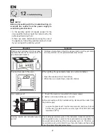
Page 13: ...RU 12 inoks 1 2 1 2 3 E14 230 25 3000C...
Page 14: ...RU 13 2002 96 MVC1 2428B 1 A 2 0 79 2 58 45 2 1080 1 G 2...
Page 24: ...05 2010 C600983I5...


