- 14 -
Installation
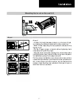
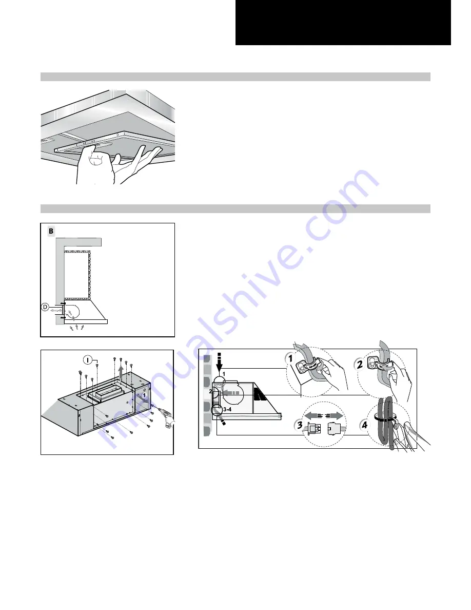
Phase 1
Phase 2
Phase 1
- Before carrying out assembly operations, open the packaging,
take the hood and place it on a comfortable surface.
- Remove the anti-grease filter/s as shown in the picture.
Phase 2
- If hood installation is used with the air outlet Fig.1B or
Fig.4B, the wires set-up in the relevant wiring harness must
be released by pulling the lever outwards, as indicated in
figure 2, phase 1-2.
- Disconnect the 6-way quick coupling of the motor located
inside of the hood, as show in figure 2. - phase 3.
- The wires positioned inside of the hood are fasted with a
cable tie. Cut the cable tie as shown in figure 2 - phase 4.
Once transformation operations have been completed,
reassemble the components following
the steps in reverse (Fig.2).
In this way it will be easier to manoeuvre the unit.
- If the appliance is to be mounted in DUCTING version,
prepare the air evacuation hole.
- It is recommended to use an air evacuation pipe with the
same diameter as the air outlet
flange. The use of a reduction could decrease product
performance and increase noise.
fig.1B
fig.4B
fig.2
Summary of Contents for PVUS930
Page 2: ......
Page 9: ... 9 Technical data 2 2 29 15 16 35 15 16 11 1 3 8 10 1 13 16 3 12 3 1 4 ...
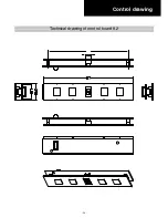
Page 20: ... 20 Control drawing Technical drawing of control board 9 2 ...
Page 28: ... 28 Electrical Assembly ...
Page 29: ... 29 Wiring Diagram ...
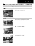
Page 32: ... 32 Phase 5 Remove all the screws indicated Motor Phase 5 ...
Page 35: ... 35 Exploded view Models PVUS930 PVUS936 ...
Page 38: ...29 5829 ...


