- 19 -
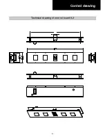
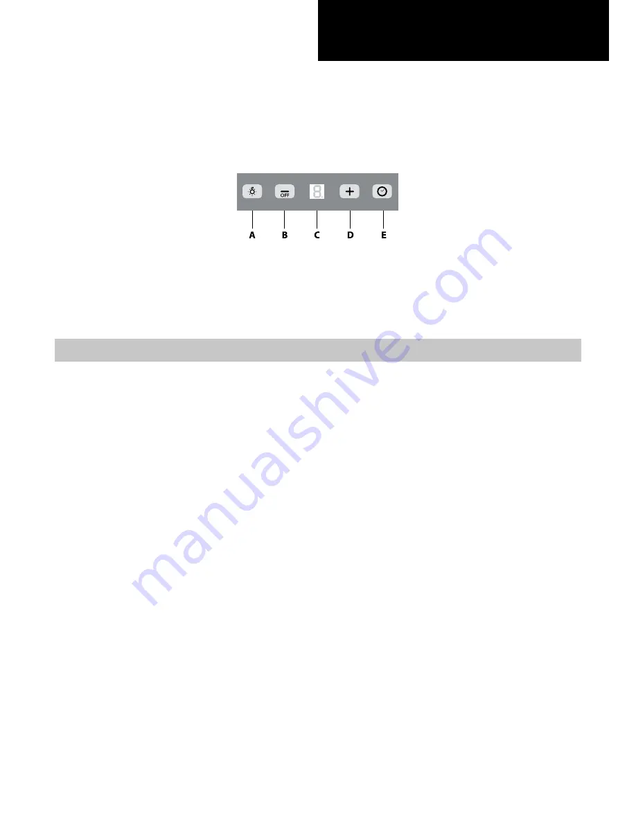
Control drawing
Confi guration 9.1
Push-button A
= On/off lights switch.
Push-button B
= On/off cooker hood switch. The appliance switches on at speed level 1, If the cooker
hood is on depress the push-button for 2 sec. to switch off the cooker hood. If the cooker hood is
at speed level 1 it will not be necessary to depress the push-button to switch the cooker hood off.
Decreases the motor speed.
Display C
= Indicates the motor speed level selected and activates the timer.
Push-button D
= Switches on the cooker hood. Increases the motor speed. Touching the key at 3rd
speed, the intensive function runs for 10 minutes, then the appliance go back to work at the original
speed. During this function the display blinks.
Key E
= The Timer times the functions on activation for 15 minutes, after which they are switched off.
The Timer is deactivated by re-pressing Key E. When the Timer is activated the decimal point must
flash on the display. The Timer cannot be activated if the intensive speed is functioning.
- The “clean air” function is activated by pressing key E for 2 seconds when the appliance is switched
off. This switches the motor on for 10 minutes every hour at the first speed.
During functioning a rotary movement of the peripheral segments must be visualised on the display.
When this time has passed the motor switches off and the fixed letter “C” must be visualised on the
display until the motor re-starts after 50 minutes for another 10 minutes and so on. Press any key apart
from the light keys to return to normal functioning. Press key E to deactivate the function.
• Active carbon/grease filter saturation:
- When display item C flashes, at a speed where it alternates with the letter F (e.g. 1 and F), the grease
filters must be washed.
- When display item C flashes, at a speed where it alternates with the letter A (e.g. 1 and A), the carbon
filters must be replaced.
After the clean filter has been positioned correctly, the electronic memory must be reset by pressing
button A for approximately 5 seconds, until the indication F or A shown on the display C stops flashing.
Summary of Contents for PVUS930
Page 2: ......
Page 9: ... 9 Technical data 2 2 29 15 16 35 15 16 11 1 3 8 10 1 13 16 3 12 3 1 4 ...
Page 20: ... 20 Control drawing Technical drawing of control board 9 2 ...
Page 28: ... 28 Electrical Assembly ...
Page 29: ... 29 Wiring Diagram ...
Page 32: ... 32 Phase 5 Remove all the screws indicated Motor Phase 5 ...
Page 35: ... 35 Exploded view Models PVUS930 PVUS936 ...
Page 38: ...29 5829 ...


