- 27 -
Power board
ATTENTION!
during the reassembling phases be carefull because there is
only one correct way to connect the cables. All the electrical
pins must be reassembled in the right position. Refer to the
wiring diagram.
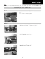
Phase 3
- Disconnect all the cables and the connector and replace the
power board.
Phase 3
Summary of Contents for PVUS930
Page 2: ......
Page 9: ... 9 Technical data 2 2 29 15 16 35 15 16 11 1 3 8 10 1 13 16 3 12 3 1 4 ...
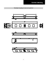
Page 20: ... 20 Control drawing Technical drawing of control board 9 2 ...
Page 28: ... 28 Electrical Assembly ...
Page 29: ... 29 Wiring Diagram ...
Page 32: ... 32 Phase 5 Remove all the screws indicated Motor Phase 5 ...
Page 35: ... 35 Exploded view Models PVUS930 PVUS936 ...
Page 38: ...29 5829 ...


