background image

13 

OPERATION INSTRUCTION 

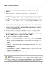
1.  Open the power switch, screen will show set current volume and ventilator is beginning to revolve. 

2.  Adjust knobs of welding current and arc-striking push, make welding function complies with 

demands. 

3.  Generally, welding current is adequate to welding electrode according with as following.


Specification

mm


Φ1.6 

Φ2.0 

φ2.5 

φ3.2


φ4.0


φ5.0


Φ6.0 

Current

A


25~40A 

40~65A 

50-90A 

90-130A 

140-210A  190-270A  260~300A 


4.  Knob of arc-striking drive is use to adjust welding function, specially in low current arrange, that is 

cooperated with knob of welding current adjustment, they may adjust current of arc striking and be 

out of control of knob of welding current adjustment .So machine can grain powerful energy and 

push current can achieve effect that may .         

5.  If the anti-shock device is installed in the machine. When the switch of back panel is put "ON" 

position, the VRD indictor is lit, and when the switch is put "OFF" position, the VRD indicator is off, 

then the no-load voltage is 60-70V. Switch of VRD is put inside the machine, with the "on" condition. 

the no-load voltage changes to be less than 15V, which is safe for people.   

6.  If welding machine has been coordinated remote control device: 

1) 

Make sure the switch position of remote control device before operation .If switch is on “OFF” 

Position that is out of remote co

ntrol. Switch is on “ON” position that is using remote control 

device. 

2)  Insert plug of remote control in socket of remote control correctly and tighten firmly in order to 

prevent poor contact. 

3)  If remote control device is not be used, make sure the switch is 

on “OFF” position, or welding 

current will not be adjusted on panel. 

7.  Hot initiation: Heavy current, perfect effect, striking easier. 


WARNING! 

Before connecting operation please make sure all the power is turned off. The right   

order is to connect the welding cable and ground cable to the machine first, and make   

sure they are firmly connected and then put the power plug to the power source. 

Summary of Contents for ARC 400IT

Page 1: ...ARC 400IT WELDING MACHINE USER MANUAL...

Page 2: ...urt or property lose if it is not followed The words after this sign means there is potential risk which may cause equipment fault or break if it is not followed Version Version YF TAE 0097 A0 Release...

Page 3: ...PARAMETERS TABLE 10 INSTALLATION INSTRUCTION 11 OPERATION INSTRUCTION 13 PANEL FUNCTION INSTRUCTION 14 NOTES OR PREVENTIVE MEASURES 15 QUESTIONS TO BE RUN INTO DURING WELDING 16 MAINTENANCE 17 TROUBL...

Page 4: ...cause choke Spark and hot workpiece after welding may cause fire Bad connected cable may cause fire Incompletion connection of workpiece side circuit may cause fire Never weld on the case of tinder st...

Page 5: ...user manual for safety Please follow the rules below to avoid electric shock Keep away from any electric parts Earth the machine and workpiece by professional personnel Cut off the power before instal...

Page 6: ...acilities to prevent hurt or poisoning by gas and other powder please To prevent oxygen deficiency air out the gas filled room which is full of CO2 and argon on the bottom When operating on trunks boi...

Page 7: ...l operate check and maintain the machine by professional person Keep your fingers hair clothes etc away from the switch parts such as the fan The wire end may deal damage please note the following Nev...

Page 8: ...se of industrial equipments e Health of people around Such as personnel using the heart pacemaker or audiphone f Equipments for adjustment and measurement g Anti disturb capability of other used equip...

Page 9: ...harder The welding machine has the following characteristics effective power saving compact stable arc good welding pool high no load voltage and good capacity of force compensation and multi use It...

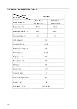
Page 10: ...15 Frequency Hz 50 60 50 60 Rated input current A 27 7 25 3 No load voltage V 62 68 VRD voltage V 18 Output current A 40 400 Rated output voltage V 36 Force range A 0 100 Duty cycle 40 No load loss W...

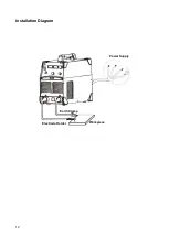
Page 11: ...s the work piece 5 Please pay attention to the connecting polarity DC welding machine has two connecting ways positive connection and negative connection Positive connection holder connects with polar...

Page 12: ...12 Installation Diagram Power Supply Workpiece Earth Clamp Electrode Holder...

Page 13: ...ictor is lit and when the switch is put OFF position the VRD indicator is off then the no load voltage is 60 70V Switch of VRD is put inside the machine with the on condition the no load voltage chang...

Page 14: ...Current adjustment knob 2 VRD switch 8 ARC force adjustment knob 3 VRD indicator 9 Hot start adjustment knob 4 Abnormal indicator 10 Positive output terminal 5 Current meter 11 Remote control socket 6...

Page 15: ...orking area is adequately ventilated It is important for the performance and the longevity of the machine 2 Do not over load The operator should remember to watch the max duty current Response to the...

Page 16: ...rom the rated value it will make the output current not matched with rated value when voltage is lower than rated value the max output may lower than rated value C Current is not stabilizing when mach...

Page 17: ...ts If scale and rust are found please clean it and connect again tightly 4 Prevent water and steam from entering into the machine If that happens please blow it dry and check insulation of machine 5 I...

Page 18: ...damaged contact with the supplier or manufacturer Abnormal indicator is on fan is working meter is normal 1 IGBT is damaged 2 Rectifier of quick recovery is damaged 3 Control board is broken 4 The fee...

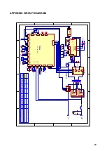
Page 19: ...4 5 CON12 XH 05 1 2 3 CON10 XH 03 1 2 3 CON8 VH 03 1 2 3 4 CON4 XH 04 1 2 3 4 5 6 CON9 XH 06 1 2 3 4 CON3 VH 04 3 1 2 3 1 2 1 2 3 CON5 VH 03 1 2 3 CON6 XH 03 1 2 CON7 XH 02 1 2 CON15 VH 02 472 3KV 47...

Page 20: ......

Page 21: ......

Reviews: