background image

Av 

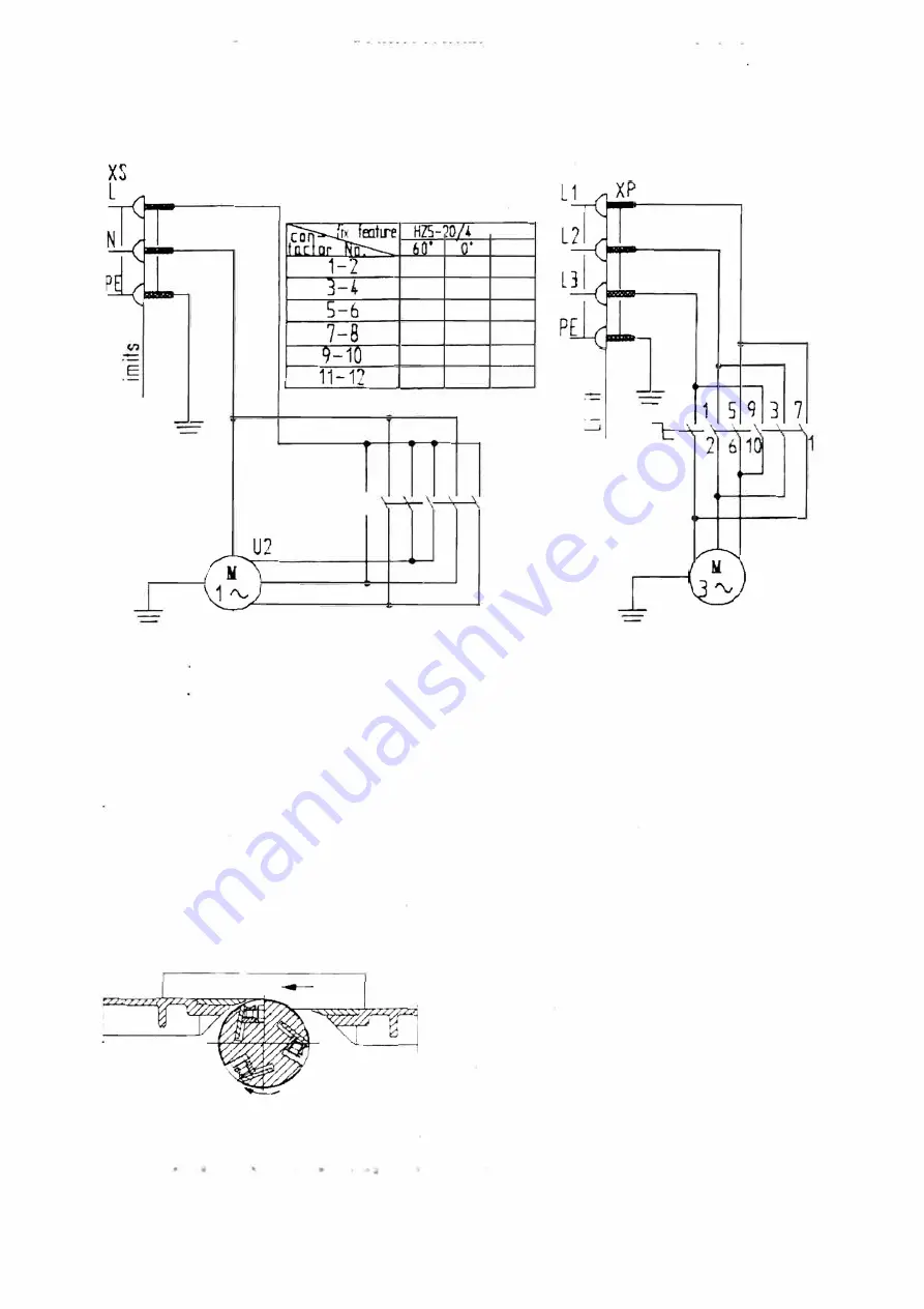
220V .SO Hz 

XP 

__J 

PE 

[}ll 

QS: 

\JI 

'/ 

Sow 

Stop  Rare 

\!/  \J/ 

HOS 

bo· 


x� 

"v 

380V .SO Hz 

PE 

V) 

QS 

�  8 

3  7  11  1  S  9 

as 

1::-\:-

4  8 12  2  6 10 

U1 

21 

PE 

22 

PE 

Note: 

0. 

1s  ma.in  winding 

U1  U2 

Z1  Z2 

1s 

the  sernnd  winding 

Fig.3 C1rcut:  diagram of ekctncai 

6 Adjustment and Application 

To guarantee security  of the operator as well  as  the  machine  nself and  improve  produces quality 
and production efficiency, it is imperative for the operator 10  master proficiently the techniques of 
adjustment and  application  of power off .The opera tar must  check the validit

and  reliability of 

mstal!ment  and  adjustment 

before 

starting 

the  machine. 

• Surface  Planer

Preparation:  Stop the machine.  move the clutch  bar 

to  planning position. 

The edges of planer tools must be straight and sharp. 

The weight of three planer tools should  be 

approximately  equal.  Shift the edges of blades to the 

same height as the  back  plane of the  bench or  0.05mm  higher  than 

it. 

Adjust height  of the front 

and  back plane  referring to the height indicating staff.  The height deviation between  two planes 

m�irns the planer depth Move the lead board 

to 

the 

right side 

of the 

bench and 

fix 

it 

during 

Summary of Contents for ML393D

Page 1: ...MODEL ML393D MULTIPLE USE WOODWORKING MACHINE SERVICE MANUAL ...

Page 2: ...rsons or things It is therefore necessary to read this manual carefully before starting the machine 2 To adjust and maintain after stopping the machine and take the plug off the socket 3 No turning the front table while the spindle is running 4 No function change while the spindle is running ...

Page 3: ... 1170mm Net weight 260kg 3 Structure This machi ne is designed with a special structure of plate combined bench type which 1s noted for tts extremely convenience and reliabilrty oi installment adjustment application and maintenance This machine is chiefly composed oi front and rear bench planes nght and left housing sheets front and back pillars elevating bench of press planer moruse ch1seling ben...

Page 4: ...d Never introduce hands arms head or other parts of the body into the machine rotating part The working area must de well illuminated without obstacles clean and without persons in it Never let keys tools or wood piece on the machine Before any cleaning or maintenance operation turn off the general s J itch of the machine and disconnect tbe plug from the feeding line Make sure that nobody may turn...

Page 5: ...he two pillars at the free state can be determined Mount up the speed change mechanism 3 as Fig l sho ed not to thread the bolts fit cham 15 V belts 9 and 4 be sure that the degree of the t1ghmess of the belts is moderate After that keep the two vertical planes of bearing base of the transfer lean against the right pillar IOclosely then thread the bolts to fasten the bearing base Then fit the prot...

Page 6: ...6 Base of mortise Chischng 7 Suppo ting Board of Circular Saw Grindmg8 Hex Head Bolt MS 10 9 Hex Head MS 20 10 Compressmg Slc e e fo hi ige omt 11 Big Control Rod 12 Square Nut 13 Hcx Head Bolt MS x 3014 Leaning Board for Mortise Chiselmg l 5 Hex lfrac Bolt M8 16 16 Mortise Chtse1n g Bench of 17 Squa e Chisel Drill 18 Socket Head Cap Screw MS 20 19 Slid wa for Tool Planer Sharpening 20 Base of Squ...

Page 7: ...stment and application of power off The operatar must check the validity and reliability of mstal ment and adjustment before starting the machine Surface Planer Preparation Stop the machine move the clutch bar to planning position The edges of planer tools must be straight and sharp The weight of three planer tools should be approximately equal Shift the edges of blades to the same height as the b...

Page 8: ...planer tools should be shifted to the same height as the step face of the rabbet to be cut or 0 05mm prolonged Lower the front bench plane to height of depth of the rabbet desired The lead board must be parallel to the stejJ face Dismount the left protectmg board of planer tool if the desired rabbet is cm the left side Othenv1se dismount the right one 1f the desired rabbet is on the nght side Mean...

Page 9: ...t the middle part of the circular saw bench may be mounted inversely Square Mortise Chiseling The square chiselmg drill must be sharp enough Keep certain gap between the back cone of the drill and inner cone of the hollow chisel while mounung up the square chiseling drill and make sure that the drill and the spmdle of the planer tool are in good coa xial Move the mortise chiseling board so that it...

Page 10: ... Sa teeth pass chrough center of the grinding wheel approximately Hold the circular saw with hand tightly Keep your body away from the grinding wheel from beginning to end Lead Board Adjustment The lead board which is ftxed to the back bench plane is not only used to for large rabbet cutting and vertical planer but also for guiding and locatmg while sawing If the circular saw bench plane is the sa...

Page 11: ...tation steadily of the tool spindle and processing quality Apply grease on eve1 sliding surface for sliding mobility 8 Tools to be Used The following tools are to be used during adjustment and maintenance l ame Specificauon I Name Specification Flat head screw driver 75 X 4 IDouble ends solid wrench 12 14 8X10 4Xl7 Cross head screw dnver 100 SO j Monkey wrench Hex socket Vrench 8 6 5 Lead weight 9...

Page 12: ...nt of heated b The motor 1s overloaded I feeding c AC supply is under voltage c Check the supply voltage I Bearing are over a Bearings are in poor lubrication Apply or exchange lubricant heated b The bearing inside is dirty Rotation is under a AC supply 1s under voltage I a Restore the supply voltage 4 I speed b The belt is loose I b Tauten the belt a The tool edge is dulled or there Planer qualit...

Reviews: