


16
NOTES OR PREVENTIVE MEASURES
1.
Environment
1
)
The machine can perform in environment where conditions are dry with a dampness level of
max 90%.
2
)
Ambient temperature is between -10 to 40 degrees centigrade.
3
)
Avoid welding in sunshine or drippings. Do not let water enter the gas.
4
)
Avoid welding in dust area or the environment with corrosive gas.
5
)
Avoid gas welding in the environment with strong airflow.
2. Safety norms
Our welding machine has installed protection circuit of over voltage, over current and over heat.
When voltage, output current and temperature of machine are exceeding the rated standard,
welding machine will stop working automatically. Because this will be damage to welding machine,
user must pay attention to following.
1
)
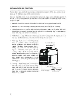
The working area is adequately ventilated
!
Our welding machine is powerful machine, when it is being operated, it generated high currents,
and natural wind cannot satisfy with machine cool demands. So there is a fan inside the
machine for its cooling demands. Make sure the intake is not in block or covered, There should
be 0.3 meter distance from welding machine to objects of environment. User should make sure
the working area is adequately ventilated. It is important for the performance and the longevity
of the machine.
2
)
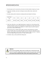
Do not over load
!
The operator should remember to watch the max duty current (Response to the selected duty
cycle) Welding current should not exceed max duty cycle current. Over-load current will
damage and burn up the machine.
3
)
No over voltage
!
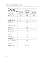
Power voltage can be found in diagram of main technical data. Automatic compensation circuit
of voltage will assure that welding current keeps is in allowable range. If power voltage is
exceeding allowable range limits, it can damage the components of machine. The operator
should understand this situation and take preventive measures.
4
)
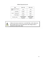
There is a grounding screw behind welding machine, with a grounding marker on it. Before
operation, welding crust must be grounded reliably with cable which section is over 6 square
millimeter, in order to prevent from static electricity, and accidents because of electricity leaking.
5
)
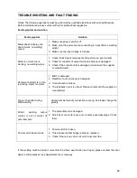
If welding time is exceeding duty cycle limited, welding machine will stop working for protection.
Because machine is overheated, temperature control switch is on “ON’’ position and the
indicator light is red. In this situation, you don’t have to pull the plug, let the fan cool the
machine. When the indicator light is off, and the temperature goes down to the standard range,
it can weld again.
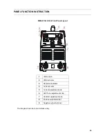
Summary of Contents for MMA 315G
Page 1: ...MMA 315G 400G WELDING MACHINE USER MANUAL ...
Page 2: ......
Page 4: ......
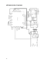
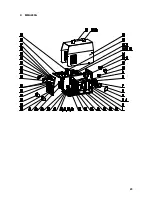
Page 22: ...20 APPENDIX Ⅰ CIRCUIT DIAGRAM ...
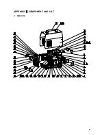
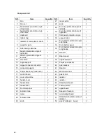
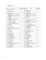
Page 23: ...21 APPENDIX Ⅱ COMPONENT AND LIST l MMA 315G ...
Page 25: ...23 l MMA 400G ...
Page 27: ......
Page 28: ......


