background image

38

39

MLMP170H51 by MacAllister

MLMP170H51 by MacAllister

In

 more 

detail

 . . .

In

 more 

detail

 . . .

Spare parts/Replacement parts

The following parts of this product may be replaced by the consumer. Spare parts are 

available at an authorised dealer or through our customer service.

Description

Blade

Code: DAYE 263001330

Repair

This product does not contain any parts that can be repaired by the consumer. Contact an 

Storage

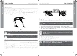
1.  Switch the product off and disconnect the spark plug connector.

2.  Clean the product as described above.

3.  Store the product and its accessories in a dry, frost-free place.

4.  Always store the product in a place that is inaccessible to children. The ideal storage 

temperature is between 10 °C and 30 °C.

5.  We recommend using the original package for storage or covering the product with 

a suitable cloth or enclosure to protect it against dust.

6.  Empty the tank if you are not going to use the product for an extended period of time 

(more than 30 days) and before storing it for the winter.

Transportation

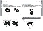
1.  Switch the product off and disconnect the spark plug connector.

2.  Adjust the height to the highest position as described above.

3.  Attach transportation guards, if applicable.

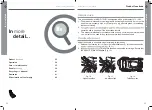
4.  Always transport the product by its handles


(1, 1a).

5.  Protect the product from any heavy impact or strong vibrations which may occur 

during transportation in vehicles.

6.  Secure the product to prevent it from slipping or falling over, loss of fuel, damage 

and injury.

Care and maintenance

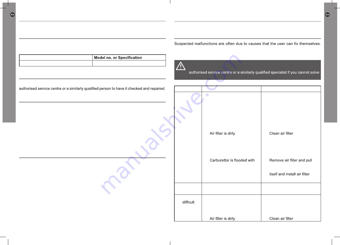
Trouble shooting

Therefore check the product using this section. In most cases the problem can be 

solved quickly.

WARNING!

 Only perform the steps described within these instructions! All 

further inspection, maintenance and repair work must be performed by an 

the problem yourself!

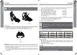
Problem

Possible cause

Solution

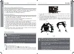
1.  Engine 

does not 

start

1.1 Not enough fuel in fuel tank

1.1 Add fuel

1.2 Spark plug is wet

1.2 Dry spark plug

1.3 Spark plug is damaged

1.3 Replace spark plug

1.4 Spark plug connector lose

1.4 Attach properly

1.5 Choke control lever not in 

the correct position for the 

prevailing conditions

1.5 Move choke control lever to 

correct position

1.6 

1.6 

1.7 Spark plug loose

1.7 Tighten spark plug 

25-30 N m

1.8 Spark plug gap is incorrect

1.8 Set gap between electrodes 

at 0.7-0.8 mm

1.9 

fuel

1.9 

recoil starter handle continu-

ously until carburettor clears 

1.10 Faulty ignition module

1.10 Contact the service agent

2.  Engine 

stops

2.1 Not enough fuel in fuel tank

2.1 Add fuel

2.2 Cutting device is blocked

2.2 Remove blockage

3.  Engine 

to start 

or loses 

power

3.1 Dirt, water or stale fuel in the 

tank

3.1 Drain fuel and clean tank. Fill 

tank with clean, fresh fuel

3.2 Vent hole in fuel tank cap is 

clogged

3.2 Clean or replace fuel tank 

cap

3.3 

3.3 

Trouble shooting

Summary of Contents for MLMP170H51

Page 1: ...ructions before using the product Original Instructions MLMP170H51 GB_V01_20181119 Manufacturer 3 Sheldon Square London W2 6PX United Kingdom Distributor B Q plc Chandlers Ford Hants SO53 3LE United K...

Page 2: ...3 Never operate the product while people especially children or pets are nearby 4 Keep in mind that the operator or user is responsible for accidents or hazards occurring to other people or their pro...

Page 3: ...sengage all cutting device and drive clutches before starting the engine 20 Start the engine or switch on the engine carefully according to instructions and with feet well away from the cutting device...

Page 4: ...wing points into account to minimize the vibration and noise exposure risks 1 Only use the product as intended by its design and these instructions 2 Ensure that the product is in good condition and w...

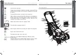
Page 5: ...of prohibited Hot surface do not touch High temperatures on the product s surfaces and structural parts that could cause burns if they are touched The product can also stay hot for a longer period of...

Page 6: ...hat other people and pets remain at a safe distance from the product when it is in operation In general children must not come near the area where the product is Release the brake bar to stop the engi...

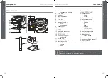
Page 7: ...ndle bar 8 Fixation lever x 2 a Lever b 9 Wire clip x 1 10 fuel tank cap 12 13 Spark plug connector 14 Wheel 15 16 17 oil tank cap 18 Lever for cutting height adjustment 19 Mounting set x 4 a Bolt b W...

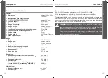
Page 8: ...2005 88 EC 98 dB A Vibration level Hand arm vibration ah w 13 49 m s2 Uncertainty K 1 5 m s2 The sound values have been determined according to noise test code given in EN ISO 5395 2 using the basic...

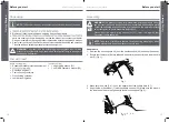
Page 9: ...l Fuel collecting container Oil collecting container Lubrication oil grease items supplied 1 x Spark plug wrench 31 1 x HONDA operator s manual 34 Assembly WARNING The product must be fully assembled...

Page 10: ...hold it in position and align the hooks on the grass catcher 22 with the rod to hang it onto it Fig 6 Fig 6 Fuel and engine oil This product is equipped with a 4 stroke engine Before operation it is n...

Page 11: ...the tank to allow for expansion Fig 8 Fig 8 NOTE you use petrol which has been kept for more than 30 days Towards the end of the season it is advisable to put only as much fuel in the tank as you nee...

Page 12: ...rt Quick start Operating controls Set up Assemble Adjust Add fuel Add oil Start Pull and hold brake lever Pull recoil starter sharply repeat until it starts Operate Stopping Release drive lever Releas...

Page 13: ...be used to mow unusually high dry or wet grass e g pasture grass for shredding leaves or mulching 2 operation and to observe all the instructions therein 3 This product is intended for private domesti...

Page 14: ...atch 22b is opened the grass catcher 22 has enough volume left to collect grass Fig A 2 When the hatch 22b is closed the grass catcher 22 is full and must be emptied Fig B Fig A Fig B Emptying Empty t...

Page 15: ...eight When mowing high grass start with the maximum cutting height and make a second cut with lower cutting height 1 Pull the lever 18 towards the wheel 14 then move it forward or backward to adjust t...

Page 16: ...ork and have full control over the product Starting Stopping WARNING Clean the underside of the deck Keep yourself ready The product will start moving forward once you hold the drive bar 3 towards the...

Page 17: ...lapping rows The most effective pattern for mowing lawns is straight lines along one of the sides This will keep the rows even and ensures that all the lawn is cut without missing any spots Fig 22 Fig...

Page 18: ...ng of the lawn Side discharging NOTE When using the side discharge function the grass clippings are discharged and spread across the ground Attach the side discharge attachment 33 Make sure the mulchi...

Page 19: ...e a worn or damaged cutting device with a new one of the same type or have it sharpened 4 Loosen the hex bolt 28f anti clockwise using a suitable wrench and remove it 28e cutting device 28 Fig 23 5 Re...

Page 20: ...y impact or strong vibrations which may occur during transportation in vehicles 6 Secure the product to prevent it from slipping or falling over loss of fuel damage and injury Care and maintenance Tro...

Page 21: ...ested to assist us and our contribution to saving resources and protecting the environment by handing in this product at an equipped collection centre if there is one available 2 Petrol oil used oil a...

Page 22: ...utdoor Noise Directive 2000 14 EC 2005 88 EC Measured Sound Power Level 93 6 dB A Guaranteed Sound Power Level 98 dB A EN ISO 3744 1995 ISO 11094 1991 Certificate registration number OR 005531 098 Tes...

Reviews: