REV A IN M02S006M-02
Page
2
of
2
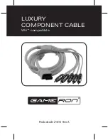
STEP 2)
Insert the Positioner into the Crimp Tool and rotate until the two Location Pins lock in place by
pushing the positioner and rotating as shown in
Fig. C.
and
D.
below.
Fig. C. (Positioner) Fig. D. (Positioner inserted into Crimp Tool)
STEP 3)
Strip wire to dimensions in “Contact Crimp Information” Table using a ruler along with a wire stripper
as shown in
Fig. E.
Fig. E
STEP 4)
Turn the Selector Knob to suit the size of wire to be crimped, (per “Contact Crimp Information Table”
above).
NOTE:
Crimp Tool Settings are based on Military Specifications Wire M22759/11xx Standard. Adjust settings to
suit other Specifications.
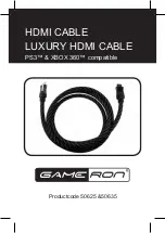
STEP 5)
Place Contact into Positioner. Insert Stripped end of wire into Contact and crimp as in
Fig. F
and
G.
Contact
Wire
Fig. F. (Contact in Positioner) Fig. G. (Wire in inserted in Contact)
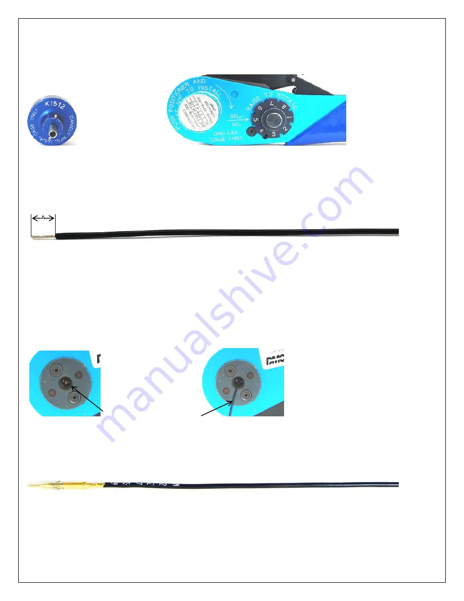
STEP 6)
Inspect crimped assembly for extruding strands of wire to prevent shorts and also check for retention
by a Pull and Return Test per
IPC/WHMA-A-620A
standard (Ch. 19.7.2) to match
Fig. G
. below.
Fig. G.