800.MACTOOLS
29
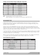
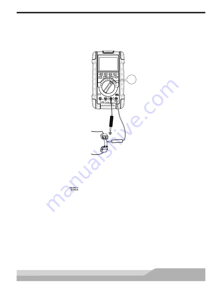
Duty Cycle Measurements
Duty cycle (or duty factor) is the percentage of time a signal is above or below a trigger level during one cycle.
There are many signals on the vehicle where you may need to measure duty cycle. For example, signals from
the mixture control solenoid of a feedback carburetor, signals from cam or crank sensors, and the control
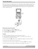
signals for fuel injectors. This example uses the meter to measure duty cycle on the mixture control solenoid
signal of a feedback carburetor.
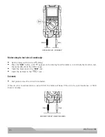
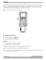
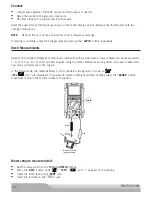
Black
Good
ground
Red
Jumper leads
from feedback
solenoid
RPM IG
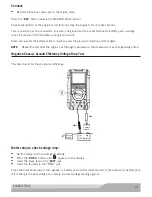
Meter setup to measure duty cycle:
•
Set the rotary switch to the RPM IG (
RPM IG
) setting.
•
Press the “
%DUTY
” button until “%” appears on the display.
•
Insert the black lead in the “
COM
” jack.
•
Insert the red lead in the “
” jack.
Connect:
•
Jumper wires between the feedback solenoid and the harness connector.
•
Black test probe to a good ground near the carburetor or the negative (-) vehicle battery post.
•
Red test probe to the solenoid control signal.
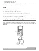
Press and hold down the “
±TRIG
” button for 1 sec to toggle between negative (-) and positive (+) slope.
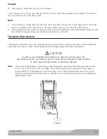
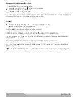
Start the engine. A duty cycle of about 50% should be read.
If reading is too high or unstable, adjust the trigger level by pressing the “
±TRIG
” button repeatedly.
For most cars, the points of the solenoid are closed for a duty cycle between 50% and 70%.

