800.MACTOOLS
57
Hall-Effect Sensor (Voltage) Test
This test checks for switching action of the Hall-Effect position sensor.
Red
Fixed position
magnet
Signal
output (+12V)
Hall-Effect
device
Switching
transistor
Insert a thin
metal blade
between Hall-
Effect device
and magnet
Connect
to battery
Black
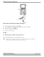
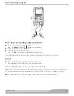
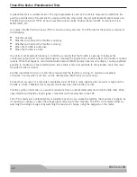
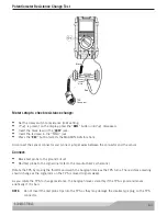
Meter setup to check Hall-Effect sensors:
•
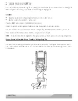
Set the rotary switch to voltage ( ) setting.
•
Insert the black lead in the “
COM
” jack.
•
Insert the red lead in the “
” jack.
Connect:
•
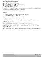
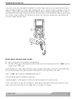
Black test probe to the ground terminal of the Hall-Effect sensor.
•
Red test probe to the signal output terminal of the Hall-Effect sensor.
Insert a thin metal blade or steel feeler gauge between the Hall-Effect device and the magnet while watching
the bargraph and the display.
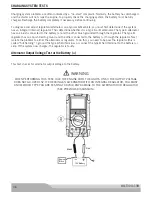
The output signal should vary from 12V to 0V. Inserting the metal blade blocks the magnetic field from getting
to the Hall-Effect sensor; removing the metal blade allows the magnetic field to reach the sensor.

