


OM-210 089 Page 21
SECTION 5 − MAINTENANCE &TROUBLESHOOTING
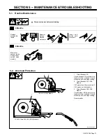
5-1.
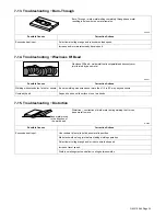
Routine Maintenance
Y
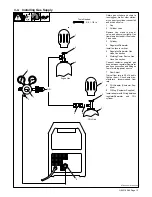
Disconnect power before maintaining.
3 Months
Replace
unreadable
labels.
Repair or
replace
cracked
weld cable.
Clean and
tighten weld
terminals.
6 Months
Blow out or
vacuum inside.
During heavy
service, clean
monthly.
Or
5-2.
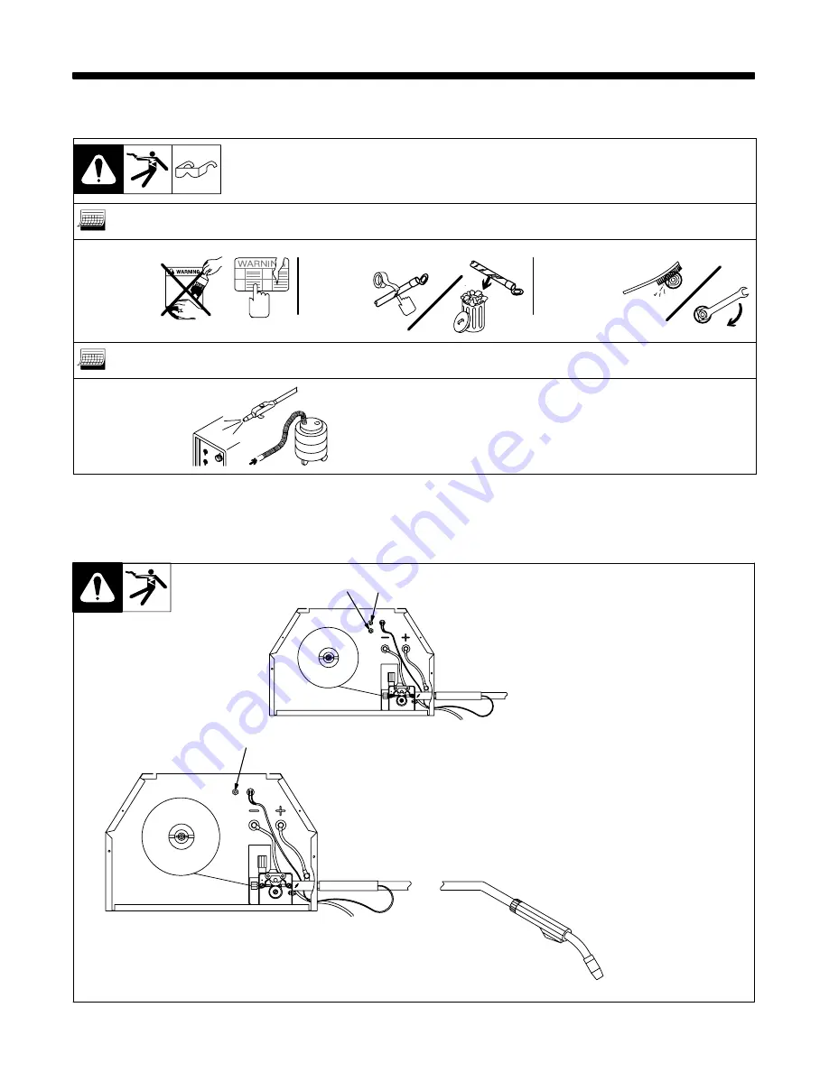
Overload Protection
Ref. ST-802 081
1
Circuit Breaker CB
Circuit breaker CB protects wire
feed motor from overload. If circuit
breaker opens, wire stops feeding.
2
Circuit Breaker CB1 (CSA
Model)
CB1 protects unit from overload. If
CB1 opens, unit shuts down.
3
Circuit Breaker CB2 (CSA
Model)
Circuit breaker CB2 protects wire
feed motor from overload. If circuit
breaker opens, wire stops feeding.
Reset breaker.
1
2
3
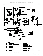
120 VAC (CSA) Model
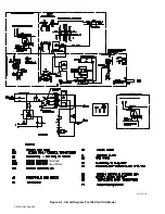
120 VAC And 230 VAC (CSA) Models
Summary of Contents for MW135
Page 2: ......
Page 4: ......
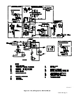
Page 31: ...OM 210 089 Page 27 ST 205 423 B 53 53 Figure 6 3 Circuit Diagram For 230 VAC Model...
Page 41: ...OM 210 089 Page 37 Notes...
Page 46: ......


