background image

OM-210 089 Page 2

Arc rays from the welding process produce intense
visible and invisible (ultraviolet and infrared) rays
that can burn eyes and skin. Sparks fly off from the
weld.

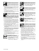
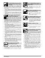
ARC RAYS can burn eyes and skin.

D

Wear a welding helmet fitted with a proper shade of filter to protect
your face and eyes when welding or watching (see ANSI Z49.1
and Z87.1 listed in Safety Standards).

D

Wear approved safety glasses with side shields under your
helmet.

D

Use protective screens or barriers to protect others from flash and
glare; warn others not to watch the arc.

D

Wear protective clothing made from durable, flame-resistant
material (leather and wool) and foot protection.

Welding on closed containers, such as tanks,
drums, or pipes, can cause them to blow up. Sparks
can fly off from the welding arc. The flying sparks,
hot workpiece, and hot equipment can cause fires

and burns. Accidental contact of electrode to metal objects can
cause sparks, explosion, overheating, or fire. Check and be sure the
area is safe before doing any welding.

WELDING can cause fire or explosion.

D

Protect yourself and others from flying sparks and hot metal.

D

Do not weld where flying sparks can strike flammable material.

D

Remove all flammables within 35 ft (10.7 m) of the welding arc. If
this is not possible, tightly cover them with approved covers.

D

Be alert that welding sparks and hot materials from welding can
easily go through small cracks and openings to adjacent areas.

D

Watch for fire, and keep a fire extinguisher nearby.

D

Be aware that welding on a ceiling, floor, bulkhead, or partition
can cause fire on the hidden side.

D

Do not weld on closed containers such as tanks, drums, or pipes,
unless they are properly prepared according to AWS F4.1 (see
Safety Standards).

D

Connect work cable to the work as close to the welding area as
practical to prevent welding current from traveling long, possibly
unknown paths and causing electric shock and fire hazards.

D

Do not use welder to thaw frozen pipes.

D

Remove stick electrode from holder or cut off welding wire at
contact tip when not in use.

D

Wear oil-free protective garments such as leather gloves, heavy
shirt, cuffless trousers, high shoes, and a cap.

D

Remove any combustibles, such as a butane lighter or matches,
from your person before doing any welding.

FLYING METAL can injure eyes.

D

Welding, chipping, wire brushing, and grinding
cause sparks and flying metal. As welds cool,
they can throw off slag.

D

Wear approved safety glasses with side
shields even under your welding helmet.

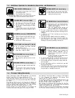
BUILDUP OF GAS can injure or kill.

D

Shut off shielding gas supply when not in use.

D

Always ventilate confined spaces or use
approved air-supplied respirator.

HOT PARTS can cause severe burns.

D

Do not touch hot parts bare handed.

D

Allow cooling period before working on gun or
torch.

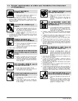
MAGNETIC FIELDS can affect pacemakers.

D

Pacemaker wearers keep away.

D

Wearers should consult their doctor before
going near arc welding, gouging, or spot
welding operations.

NOISE can damage hearing.

Noise from some processes or equipment can
damage hearing.

D

Wear approved ear protection if noise level is
high.

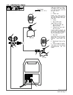
Shielding gas cylinders contain gas under high
pressure. If damaged, a cylinder can explode.
Since gas cylinders are normally part of the welding
process, be sure to treat them carefully.

CYLINDERS can explode if damaged.

D

Protect compressed gas cylinders from excessive heat,
mechanical shocks, slag, open flames, sparks, and arcs.

D

Install cylinders in an upright position by securing to a stationary
support or cylinder rack to prevent falling or tipping.

D

Keep cylinders away from any welding or other electrical circuits.

D

Never drape a welding torch over a gas cylinder.

D

Never allow a welding electrode to touch any cylinder.

D

Never weld on a pressurized cylinder − explosion will result.

D

Use only correct shielding gas cylinders, regulators, hoses, and
fittings designed for the specific application; maintain them and
associated parts in good condition.

D

Turn face away from valve outlet when opening cylinder valve.

D

Keep protective cap in place over valve except when cylinder is in
use or connected for use.

D

Read and follow instructions on compressed gas cylinders,
associated equipment, and CGA publication P-1 listed in Safety
Standards.

Summary of Contents for MW135

Page 1: ...Processes OM 210 089B September1998 MW 135 MW 175 And GA16C2 Gun Arc Welding Power Source And Wire Feeder Description MIG GMAW Welding Flux Cored FCAW Welding...

Page 2: ......

Page 3: ...30 VAC Model 16 3 8 Installing Wire Spool And Adjusting Hub Tension 16 3 9 Threading Welding Wire 17 SECTION 4 OPERATION 18 4 1 Controls 18 4 2 Weld Parameters For 120 VAC Model 19 4 3 Weld Parameters...

Page 4: ......

Page 5: ...is connected to a properly grounded receptacle outlet D When making input connections attach proper grounding conductor first double check connections D Frequently inspect input power cord for damage...

Page 6: ...welding wire at contact tip when not in use D Wear oil free protective garments such as leather gloves heavy shirt cuffless trousers high shoes and a cap D Remove any combustibles such as a butane lig...

Page 7: ...maintained D Keep high frequency source doors and panels tightly shut keep spark gaps at correct setting and use grounding and shielding to minimize the possibility of interference ARC WELDING can ca...

Page 8: ...is a human health hazard However studies are still going forth and evidence continues to be examined Until the final conclusions of the research are reached you may wish to minimize your exposure to...

Page 9: ...rne de terre du sectionneur ou que la fiche du cordon est raccord e une prise correctement mise la terre D En effectuant les raccordements d entr e fixer d abord le conducteur de mise la terre appropr...

Page 10: ...ter des v tements de protection d pourvus d huile tels que des gants en cuir une chemise en mat riau lourd des pantalons sans re vers des chaussures hautes et un couvre chef D Avant de souder retirer...

Page 11: ...uvrements et dispositifs de protection LE RAYONNEMENT HAUTE FR QUENCE H F risque de provoquer des interf rences D Le rayonnement haute frequence peut provoquer des interf rences avec les quipements de...

Page 12: ...sions g n rales du document intitu l Biological Effects of Power Frequency Electric Magnetic Fields Background Paper OTA BP E 53 Washington DC U S Govern ment Printing Office mai 1989 publi par le Off...

Page 13: ...Wire Feed Speed Range At No Load Wire Type And Dia 023 030 in 0 6 0 8 mm 030 035 in 0 8 0 9 mm 160 870 IPM 4 1 22 5 m min CSA Rating B 230 VAC Model Rated Welding Output Amperage Range Maximum Open C...

Page 14: ...fifteen minutes for unit to cool Reduce amperage or duty cycle before welding Y Exceeding duty cycle can damage unit or gun and void warranty Overheating 0 15 A or V OR Reduce Duty Cycle Minutes duty1...

Page 15: ...he volt ampere curves show the minimum and maximum voltage and amperage output capabilities of the welding power source Curves of other settings fall be tween the curves shown ssb1 1 10 91 ST 802 082...

Page 16: ...2 3 3 2 Changing Polarity 1 Lead Connections For Direct Current Electrode Positive DCEP 2 Lead Connections For Direct Current Electrode Negative DCEN Always read and follow wire manufacturer s recomm...

Page 17: ...rtical 5 Regulator Flowmeter Gas Hose Connection 6 Welding Power Source Gas Hose Connection Connect customer supplied gas hose between regulator flowmeter gas hose connection and fitting on rear of we...

Page 18: ...dual branch circuit protected by time delay fuses or circuit breaker is required 3 Plug From Unit Select extension cord of 14 AWG for up to 50 ft 15 m or 12 AWG for 50 up to 200 ft 61 m Y Special inst...

Page 19: ...receptacle 4 Line Disconnect Device See Section 3 7 Y Special installation may be required where gasoline or volatile liquids are present see NEC Article 511 or CEC Section 20 ssb2 2 1 94 Ref ST 802...

Page 20: ...4 Max Recommended Input Conductor Length In Feet Meters 66 20 Min Grounding Conductor Size In AWG Kcmil 14 Reference 1996 National Electrical Code NEC S 0092 J 3 8 Installing Wire Spool And Adjusting...

Page 21: ...mm Tighten Remove gun nozzle and contact tip Open pressure assembly Push wire thru guides into gun continue to hold wire Close and tighten pressure assembly and let go of wire Hold wire tightly to ke...

Page 22: ...on fan runs but there is no weld output 3 Wire Speed Control Use control to select a wire feed speed As Voltage switch setting increases wire speed range also increases see weld setting label in weldi...

Page 23: ...es Door Hinge Bailers Combines Bumpers Brackets Grain Wagons Wheelbarrows Garage Door Trailers Trailer Frames Fencing Lawnmower Decks Work Auto Door Brackets Galvanized Roofing Trailer Sides Garage Do...

Page 24: ...EP DCEP DCEP DCEN DCEN DCEN DCEN DCEN DCEN DCEN DCEP 1 2 2 1 2 2 2 1 1 3 3 3 2 2 4 4 4 3or4 3or4 3 2 1 9 6 7 4 5 5 5 4 5 5 4 5 6 7 7 8 4 5 5 6 4 5 4 5 5 5 6 7 5 5 5 4 5 3 4 4 5 5 5 4 5 5 4 5 4 5 5 5 4...

Page 25: ...e clean monthly Or 5 2 Overload Protection Ref ST 802 081 1 Circuit Breaker CB Circuit breaker CB protects wire feed motor from overload If circuit breaker opens wire stops feeding 2 Circuit Breaker C...

Page 26: ...of the drive roll The groove closest to the motor shaft is the proper groove to thread see Section 3 9 NOTE when chang ing drive rolls make sure the woodruff key is on the motor shaft and not in the...

Page 27: ...tall collet onto liner and tighten into gun feeder connector using wrench Cut liner off near collet so that liner end is as close to drive rolls as possible without touching Install nozzle Remove nozz...

Page 28: ...tions see Section 3 2 Low weld output Connect unit to proper input voltage or check for low line voltage Place voltage switch in desired position see Section 4 1 Electrode wire feeding stops during we...

Page 29: ...OM 210 089 Page 25 SECTION 6 ELECTRICAL DIAGRAM ST 205 400 53 Figure 6 1 Circuit Diagram For 120 VAC Model...

Page 30: ...OM 210 089 Page 26 ST 210 011 B 53 17 Overload Feed Motor Figure 6 2 Circuit Diagram For 120 VAC CSA Model...

Page 31: ...OM 210 089 Page 27 ST 205 423 B 53 53 Figure 6 3 Circuit Diagram For 230 VAC Model...

Page 32: ...ctions Y Weld current can damage electronic parts in vehicles Disconnect both battery cables before welding on a vehicle Place work clamp as close to the weld as possible Wire Feeder Power Source Work...

Page 33: ...35 in 023 in 40 145 A 50 180 A 30 90 A 035 in Select Wire Speed Select Voltage Wire Recommendation 030 in 035 in 023 in 2 in per ampere 1 6 in per ampere 3 5 in per ampere Wire Speed 2 x 125 A 250 ipm...

Page 34: ...13 mm past end of nozzle and tip of wire is positioned correctly on seam NOTE 1 Hold Gun and Control Gun Trigger 2 Workpiece 3 Work Clamp 4 Electrode Extension Stickout 1 4 to 1 2 in 6 To 13 mm 5 Crad...

Page 35: ...ctrode extension stickout travel speed thickness of base metal wire feed speed weld current and voltage NOTE Short Normal Long Short Normal Long 10 10 GUN ANGLES AND WELD BEAD PROFILES ELECTRODE EXTEN...

Page 36: ...ment Along Seam 3 Weave Patterns Use weave patterns to cover a wide area in one pass of the electrode S 0054 A 3 1 2 7 6 Poor Weld Bead Characteristics 1 Large Spatter Deposits 2 Rough Uneven Bead 3 S...

Page 37: ...or liner 7 9 Troubleshooting Porosity Porosity small cavities or holes resulting from gas pockets in weld metal S 0635 Possible Causes Corrective Actions Insufficient shielding gas at welding arc Incr...

Page 38: ...f 0 to 15 degrees to achieve maximum penetration Keep arc on leading edge of weld puddle Be sure welding wire extends not more than 1 2 in 13 mm beyond nozzle Insufficient heat input Select higher wir...

Page 39: ...es Corrective Actions Welding wire extends too far out of nozzle Be sure welding wire extends not more than 1 2 in 13 mm beyond nozzle Unsteady hand Support hand on solid surface or use two hands 7 15...

Page 40: ...e most commonly used shielding gases are listed in the following table Application Gas Spray Arc Steel Short Circuiting Steel Short Circuiting Stainless Steel Short Circuiting Aluminum Argon All Posit...

Page 41: ...OM 210 089 Page 37 Notes...

Page 42: ...OM 210 089 Page 38 SECTION 8 PARTS LIST Hardware is common and not available unless listed ST 802 066 Figure 8 1 Main Assembly...

Page 43: ...sy 120 VAC model 1 24 184 735 GUIDE wire output 1 25 205 419 TRANSFORMER power assembly 230 VAC model 1 25 210 000 TRANSFORMER power assembly 120 VAC model 1 26 205 398A BRACKET mtg fan motor and heat...

Page 44: ...LE power assembly 120 VAC model 1 60 201 234 3 LEAD ground 6 1 61 205 424A LABEL door 230 VAC model 1 61 205 406A LABEL door 120 VAC model 1 405 548 LABEL ground screw not shown 1 62 406 636 LABEL mov...

Page 45: ...9 M154 825 TIP contact 030 1 9 M154 824 TIP contact 035 1 10 110 794 TRIGGER SWITCH ASSEMBLY 1 11 110 792 CABLE 10ft 1 12 110 797 SLEEVE rubber 1 13 167 440 LINER monocoil 023 035 wire 10ft consistin...

Page 46: ......

Reviews: