OM-154 500 Page 15
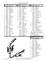
Parts For Main Assembly
NOTE: All items indented by a dot(s) are included with the item listed directly above.
Description
Part
No.
Item
No.
Part
No.
Item
No.
Description
Part
No.
Item
No.
Description
1
089 899
Latch
2
134 464
Warning Label
3
+151 565
Wrapper
126 838
Drive Assembly
4
124 817
· Drive Housing
5
090 416
· Hinge Pin
6
151 828
· Cotter Hair Pin
7
112 031
· Pressure Lever
8
090 443
· Bearing
111 622
· · Spacer
9
092 237
· Knob
10
090 415
· Spring
11
085 244
· Cupped Washer
12
085 242
· Fastener
13
010 224
· Spring Pin
14
058 549
· Wire Guide
15
126 652
Knob
16
149 332
Hose Clamp
17
134 834
Hose
18
154 828
Drive Roll
19
126 653
Nyl Washer
20
111 912
Insulator
21
147 573
Bracket
22
126 651
Nyl Shldr Washer
23
048 573
Light
24
058 428
Hub
25
057 745
Spring
26
058 628
Brake Washer
27
010 191
Fiber Washer
28
057 971
Keyed Washer
29
057 543
Spring
30
605 941
Washer
31
058 427
Retaining Ring
32
085 980
Nut
33
134 201
Stand-Off Support
34
057 358
Bushing
35
147 569
Baffle
36
108 358
Contactor
37
157 044
Circuit Card
38
*125 847
· Fuse, slo-blo 12A
113 149
Housing, 14 pin
079 747
Terminal
39
072 817
Relay
40
087 156
Varistor
41
155 056
Rectifier
155 054
· Thermostat, NC
026 701
· Insulation
42
152 214
Terminal Assembly
038 618
· Link
43
090 087
Drive Motor
44
112 583
Insulator
45
123 770
Resistor Assembly
117 116
· Resistor
46
162 245
Capacitor
47
022 160
Clamp
48
Base w/Running Gear
152 872
· Base
147 893
· Axle
090 693
· Wheel, 8 in
602 250
· Washer, .750 flat
121 614
· Retaining Ring
109 318
· Caster, 2.500
49
117 014
Fan Motor
50
005 656
Fan Blade
51
147 572
Bracket
52
Rear Panel w/Cmpts
128 751
· Gas Valve
605 227
· Nyl Nut, gas valve
152 118
· Cord Set
111 443
· Bushing, cord set
147 443
· Rear Panel
146 619
· Bezel
147 548
· Speed Nut
156 339
· Bottle Retainer
602 389
· S Hook
156 340
· Chain
602 384
· Snap, chain
53
147 315
Stabilizer
54
147 313
Transformer
146 943
· Coil
55
147 576
Lower Panel
56
Front Panel w/Cmpts
072 623
· Potentiometer
097 922
· Knob
048 482
· Receptacle w/Sockets
079 534
· · Terminal
111 897
· Rotary Switch, 4posn
127 023
· · Knob
116 830
· Rocker Switch, DPST
147 442
· Front Panel
146 619
· Bezel
147 548
· Speed Nut
154 005
· Handle
154 596
· Cap, Handle
153 448
· Nameplate
004 214
· Bushing, 2.000mtg
111 644
· Bushing, .875mtg
57
600 325
Cable
58
026 843
Insulator
59
010 368
Clamp
60
110 720
GA-16C Gun, (Fig 6-2)
153 714
Regulator/Flowmeter
154 829
Hose Kit
112 863
· Adapter Fitting
113 129
· PVC Tubing
089 120
· Hose Clamp, .375–.450
028 509
Regulator Adapter
+When ordering a component originally dis-
playing a precautionary label, the label should
also be ordered.
*Recommended Spare Parts.
Be sure to provide Model and Serial Number
when ordering replacement parts.
ST-110 832-D
1
110 793
Handle Assembly
110 795
Head Tube
2
110 780
· Nut
3
110 779
· Jacket
4
110 781
· Stop
5
128 878
· Adapter
6
154 819
· Spring
7
154 826
Contact Tube, .023
7
154 825
Contact Tube, .030
7
154 824
Contact Tube, .035
8
154 822
Nozzle, 1/2 orf
8
♦
154 821
Nozzle, 3/8 orf
8
♦
154 820
Nozzle, flat spot
9
110 794
Trigger Switch Assembly
10
080 565
Terminal
11
110 792
Cable
12
110 797
Sleeve
13
167 440
Liner, .023-.035
14
120 715
· Collet, .035
15
079 974
O-Ring, .500
16
110 796
Connector
17
079 878
Housing Plug & Pins
079 535
· Terminal
18
048 834
Clamp
♦
OPTIONAL
Part
No.
Item
No.
Description
1
2
3
4
5
6
7
8
9
1
10
1
11
12
13
14
15
16
17
18
2
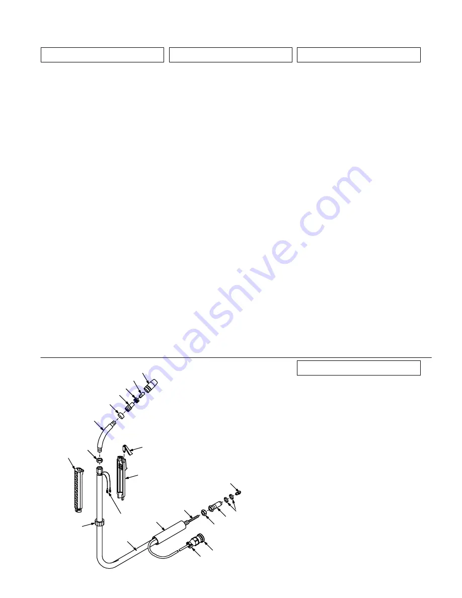
Figure 6-2. GA-16C Gun (Fig 6-1 Item 60)
Summary of Contents for MW150K
Page 16: ...OM 154 500 Page 13 Figure 5 2 Wiring Diagram For Welding Power Source SC 163 085...
Page 19: ...Notes...
Page 20: ......


