OM-154 501 Page 8
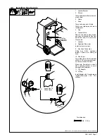
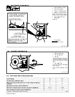
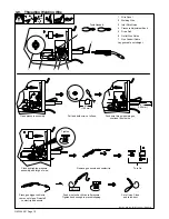
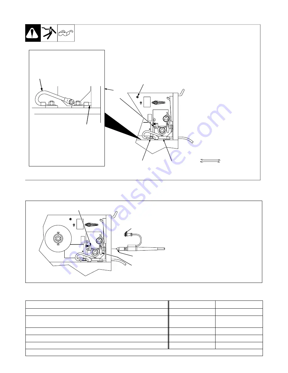
3-3. Gun Polarity Connections
1
Polarity Changeover Label
2
Wire Drive Assembly
3
Positive (+) Output Terminal
4
Negative (
−
) Output Terminal
Always read and follow wire man-
ufacturer’s recommended polarity.
5
Circuit Breaker CB1 (see
Section 5-2).
Close door.
Ref. ST-801 103-B
1
2
3
4
5
Shown As Shipped
−
Set For Electrode
Positive (DCEP) For Solid Steel Or
Aluminum Wires (GMAW Process).
Wire Drive Assembly Lead
To Positive (+) Output Terminal
Work Clamp Lead To
Negative (
−
) Output Terminal
GUN POLARITY
CHANGEOVER CONNECTIONS
Reverse Lead Connections
−
For Electrode
Negative (DCEN) For Flux Cored Wires
(FCAW Process). Drive Assembly
Becomes Negative
S-144 449-D
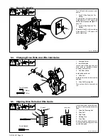
Tools Needed:
3/4, 11/16 in
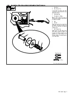
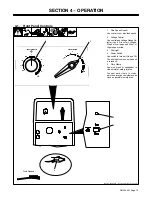
3-4. Installing Welding Gun
1
Wire Drive Assembly
2
Gun Securing Knob
3
Gun End
Loosen securing knob. Insert gun
end through opening until it bottoms
against drive assembly. Tighten
knob.
4
Gun Trigger Plug
Insert into receptacle, and tighten
threaded collar.
Close pressure assembly. Close
door.
3
4
1
2
Ref. ST-801 101-B
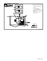
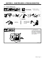
3-5. Electrical Service Requirements
Input Voltage
200
230
Input Amperes At Rated Output
46
40
Max Recommended Standard Fuse Or Circuit Breaker Rating In
Amperes
70
60
Min Input Conductor Size In AWG/Kcmil
8
8
Max Recommended Input Conductor Length
In Feet (Meters)
89 (27)
117 (36)
Min Grounding Conductor Size In AWG/Kcmil
8
10
Reference: 1996 National Electrical Code (NEC).
S-0092J


