Form # 46584
Issue 11/06 Web Rev_01
99
MAINTENANCE/SERVICE
Traction Drive: Neutral Lock and
Steering Checks (continued)
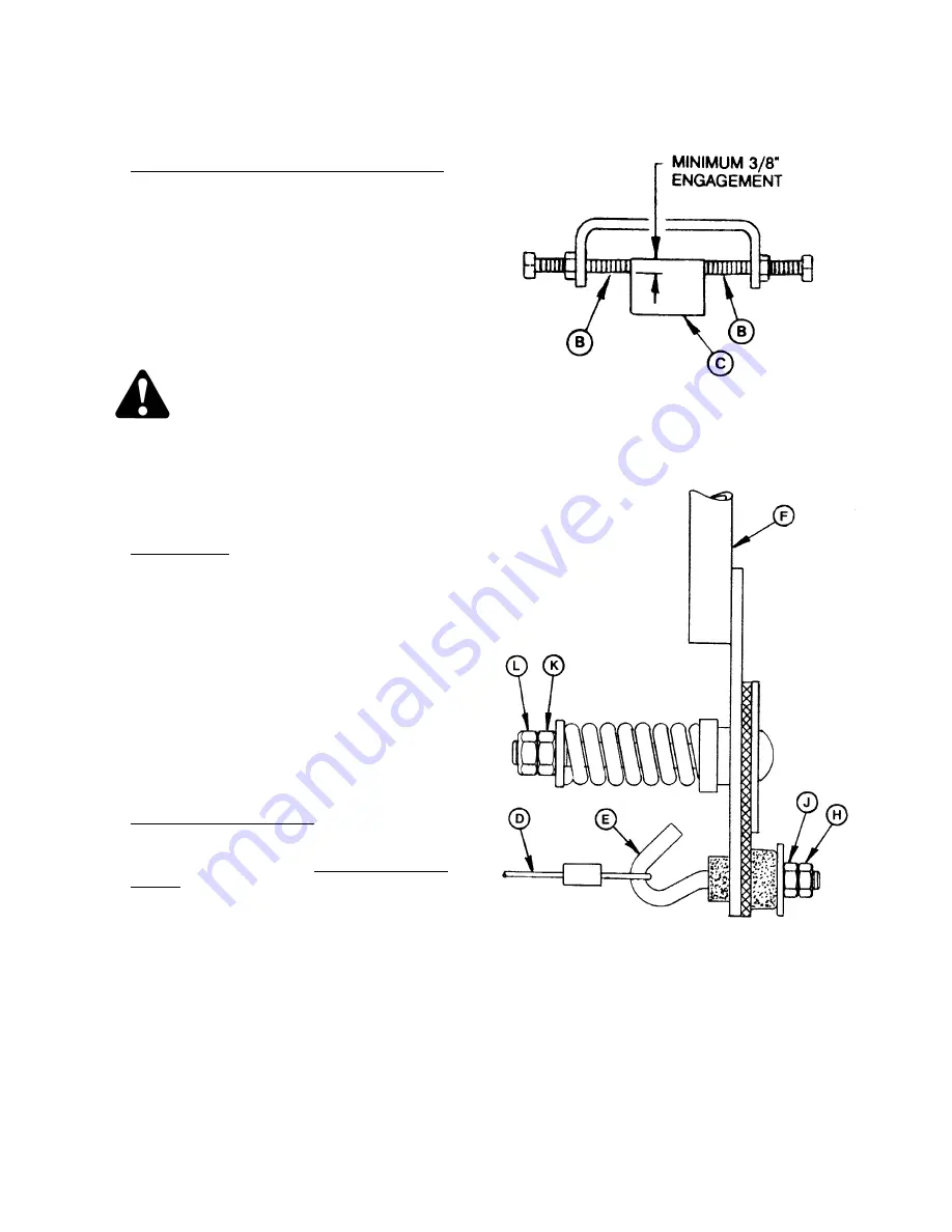
3. Neutral Lock Adjustment Bolts Engagement:
Check the depth of engagement of the neutral
lock adjustment bolts (B) on pintle arms (C).
Minimum engagement is 3/8 inch (10 mm), that
is, the full diameter of the bolt must contact
pintle arms.
To adjust:
a. Loosen cable as described in check 4, below.
b. Adjust neutral start switch to obtain proper
engagement depth.
c. Readjust cable as described in check 4.
WARNING: Do not adjust the neutral
lock adjustment bolts (B). These
bolts can only be adjusted during
neutral set-up procedure described
at the end of this section.
4. Cable Tension: Check tension of cable (D). The
cable should be tight when the ground speed
lever (F) is at the right hand side of the neutral
detent on side console, and when the neutral
start switch is fully compressed. If the cable is
too tight, it will prevent the neutral start switch
from fully compressing and prevent proper
engagement of adjustment bolts on pintle arms.
To adjust cable tension, loosen nut (H) on
threaded hook bolt (E) and turn nut (J)
clockwise to increase cable tension, counter-
clockwise to decrease. Tighten nut (H) against
nut (J) to secure the position.
5. Ground Speed Lever Pivot: Check the pivot at
ground speed lever (F). Nut (L) should be flush
with the end of the carriage bolt (full thread
engagement). To tighten, hold nut (K) with a
wrench and tighten nut (L) against nut (K).
Torque nut (L) to 60 to 70 ft.lbs. (80 to 90 N
⋅
m).
ENGAGEMENT DEPTH:
NEUTRAL LOCK ADJUSTMENT BOLTS
GROUND SPEED LEVER CONNECTIONS
Summary of Contents for 9250
Page 10: ...Form 46584 Issue 11 06 Web Rev_01 8 SAFETY SAFETY SIGNS continued...
Page 152: ......
Page 154: ......
Page 159: ...Form 46584 Issue 11 06 Header Drive Hydraulic Schematic...


